Effective March, 1998
IL 33-A1C-1
Page 4
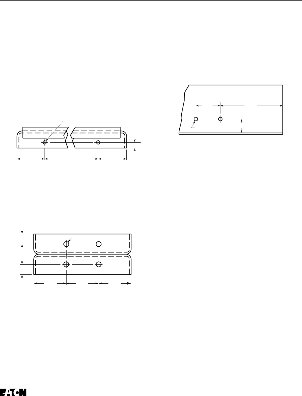
Step 3: Drilling the Mounting Holes Needed
for the Retrofit
Note: Throughout this step, cover the region
below the area being drilled to prevent metal
shavings from falling into the Breaker.
A. Using Drilling Plan “A”, drill two (2) .312" holes
in the top flange of the Breaker Back Plate.
These holes will be used to mount the Aux. CT
Module later in the Retrofit process.
B. Using Drilling Plan “B”, drill four (4) .219" holes
in the top front of the Breaker Frame. These
holes will be used to mount the Trip Unit later in
the Retrofit process.
For Kits Supplied with a Breaker Mounted
CPT Only.
C. Using Drilling Plan “C”, drill two .266" holes in
the left Breaker Frame. These holes will be used
to mount the Breaker Mounted CPT later in the
Retrofit process.
D. Remove the Finger Clusters from either the
Phase 1 & 2, or Phase 2 & 3 top Breaker Stabs.
Save the Finger Clusters and the mounting
hardware for use later in the Retrofit process.
Position a Sensor Spacer over one of the top
Breaker Stabs. Using the Sensor Spacer as a
guide, mark the location of the hole on the
Breaker Stab. Drill one (1) .219" hole through
the Breaker Stab. Repeat the procedure for the
other Breaker Stab. These holes will be used to
mount the HV Wires later in the Retrofit process.
Note: The power convention of Circuit
Breakers is normally Top to Bottom, mean-
ing the Top Breaker Stabs are on the
Line
Side
of the Breaker and the Bottom Breaker
Stabs are on the
Load Side
.
The HV Wires from the CPT MUST BE
ATTACHED to the
Line Side
of the Breaker.
If it is determined that the power flow for the
Breaker application is opposite the normal
convention, the HV Wires must be attached
to the Bottom Breaker Studs.
Looking into the Breaker from the front,
the right hex bolt on the Phase 1 and 2 or
Phase 2 and 3 Bottom Breaker Studs can
be used to mount the HV Wires.
0.44”
1.00”
0.44”
1.50” 1.50” 1.50”
Front
0.219” Dia. (4)
Drilling Plan “A”
11.00" 4.12"4.12"
0.50"
0.312" Dia. (2)
Rear of Breaker
Drilling Plan “B”
Drilling Plan “C”
1.62"
1.00"
4.19"
0.266" Dia. (2)


