99922203487
10/01
SUP22203487
SUPPLEMENT TO OPERATOR'S MANUAL
PART NUMBER X7501126900 (X750003020)
FOR MODEL: PB-650
SUPPLÉMENT AU MANUEL DE L’OPÉRATEUR
RÉFÉRENCE X7501126900 (X750003020)
POUR MODÈL: PB-650
EMISSION C ONTROL
PAGE
6
EPA Phase I
The emission control system for this engine is EM (Engine Modification).
An Emission Control Label is located on the unit. (This is an EXAMPLE ONLY,
information on label varies by engine FAMILY).
IMPORTANT ENGINE INFORMATION
ENGINE FAMILY: 1EHXS.635RA
DISPLACEMENT: 63.3 CC
THIS ENGINE MEETS U.S. EPA PH1 EMISSION REGULATIONS
FOR SMALL NON ROAD ENGINES. REFER TO OWNER'S
MANUAL FOR MAINTENANCE SPECIFICATIONS AND ADJUST-
MENTS.
ASSEMBLY
INSTALL
BLOWER PIPES/STICK HANDLE
PAGE
9
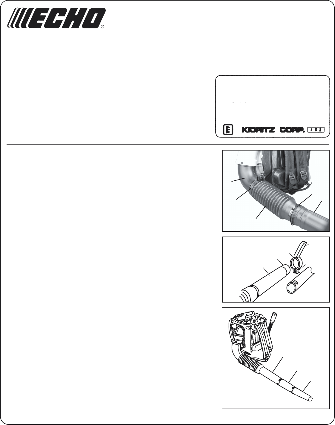
1. Assemble clamps (A) onto both ends of flexible pipe (B).
2. Assemble straight pipe with swivel (C) into flexible pipe (B).
3. Assemble flexible pipe (B) to elbow (D) on blower.
4. Tighten clamps (A).
5. Loosen wing nut (E) completely and expand open, stick handle clamp (F).
6. Align notches (G) in handle clamp with pipe pegs (H). Stick handle should
be angled away from operator.
7. Slide stick handle onto pipe with swivel (C)
8. Position stick handle for comfortable operation, and tighten wing nut (E).
9. Assemble straight pipe (J) to pipe with swivel (C), turning straight pipe
counter-clockwise to lock in place.
10. Assemble straight pipe (K) to straight pipe (J) turning straight pipe (K)
counter-clockwise to lock in place.
C
A
B
A
D
C
H
G
F
E
J
K
C
Please use these revised instructions when
assembling and stopping your Power Blower.
