EPSON Stylus Color 600
Rev. A
2-3
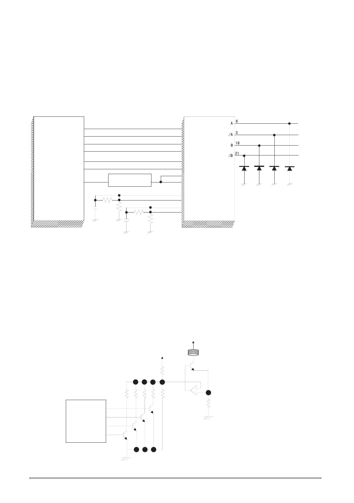
2.2.2.7 PF(Pump) Motor Drive Circuit
IC15(UDN2917) is used for driving PF(Pump) motor. In the IC, Bi-pola drive PWM current control type is
performed, making it possible to provide stable current to each phase of motor. Also, it makes possible to
change over the reference voltage as drive current settings by making 3 combinations(100%,66% and
33%), using 4 current setting ports(input). (Refer to 2.1.1.3 for motor and details about sequence) However,
firmware does not drive Micro-step in the Stylus Color 600. The figure below shows the block diagram of
Unlike using Uni-Pola drive, there is no cable for GND in the motor since Bi-Pola drive is performed in the
PF motor.(Refer to section 2.1.1.2 since carriage motor interior connection diagram has the same
connection as the PF motor’s phase connection. This helps to understand the reason why the direction of
current is controlled freely in each phase by the combinations of high/low control signals.
The current control is performed by output port(46•`49 pin) of E05B43(IC2), its outer resistance circuit and
driver IC15(UDN2917). First, firmware possesses 16 ways of current values as current table out of
combinations made by 5 resistance which are connected to the output ports(46•`49 pin) in the gate array.
On the other hand, signals which are output by combination of these resistance’s on/off are input in the 25
and 44 pins. HIC is driven at the same standard voltage for each A and B phase.
Actual on/off control to send electricity through the motor is performed by the process that SEN1 and
SEN2 terminals (2 and 13 pin) detect the input signal from the gate array which is monitored by the
interior comparator, confirm the current that actually flew the phase as current value again and
perform the feed back to the on/off. The figure below shows relation between input signal to the
driver IC and motor control.
PFA
PF/A
PFB
PF/B
I10
I11
I20
I21
2
1
23
24
Vref1
Vref2
SENS1
E1
SENS2
E2
PFA0
PFA1
PFB0
PFB1
57
58
55
56
59
50
PFAPH
PFBPH
43
26
PH1
PH2
PFV0-PFV3
46-49
44
25
1
2
3
4
4
5
Current Selection
Resistor
E05B43(IC2)
UDN2917(IC15)
Figure 2-27. PF(Pump) Motor Circuit Block Diagram
E05B43(IC2)
Gate Array
+5V
+42V
RS
R1
R2 R3
R4
Ra
Rb
UDN2917(IC14,IC15)
In case of PF motor,
same reference voltage
is input to UDN2917 for
both phase A and B, but
differet reference voltage
is set individually for
phase A and B, in case of
CR motor.
Note:
It varies load resistance
by the control signal and
changes the ratio of partial
pressure.
If feeds back the current
that actually flew in the
coil to the comparator.
Figure 2-28. PF(Pump) Motor Driver Internal Block Diagram


