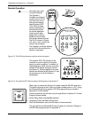
RS-232 Programming • Appendix A
Extron • System 5
cr
Switcher • User’s Manual
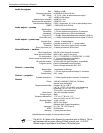
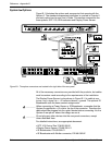
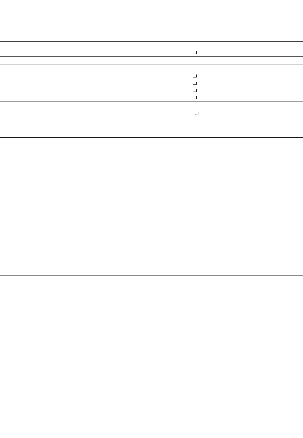
Advanced Instructions – Reserved for Windows program
IR Block ASCII Hex Unit response
Read (Upload) n/a 80 83 8k bytes of data
Write (Download) n/a 80 82 [8k bytes] Dnl
Flag Block ASCII Hex Unit response
Read (Upload) n/a 80 85 15 bytes of data
Write (Download) n/a [Byte0]*[Byte1]91 Dnl
n/a [Byte2]*[Byte3]93 Dnl
n/a [Byte6]*[Byte7]97 Dnl
n/a [Byte8]* 30 99 Dnl
Unit Reset ASCII Hex Unit response
Reset Unit n/a 80 81 Upd
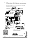
Flag Block: Consists of fifteen bytes (0-14) that will used for handling special functions for current and future operation.
Byte 0 – Power on delay
Byte 1 – Power off delay
Byte 2 – Triple action switching delay (.5 second * value)
Byte 3 – Relay control
Byte 4 – n/u
Byte 5 – n/u
Byte 6 – n/u
Byte 7 – Mute control & misc. flags
(msb) Bit 7 - True = Mute audio upon display-power down.
Bit 6 - True = Limit System volume upon switcher power up.
Bit 5 - True = Send responses to RS-232 commands.
Bit 4 - True = Send channel IR command upon display-power up.
Bit 3 - True = Enable front panel volume
Bit 2 - reserved
Bit 1 - reserved
(lsb) Bit 0 - reserved
Note: Factory default = all bits on (hex FF).
Byte 8 – Video type (composite video or S-video)
Byte 14 - Checksum
A-3