FOAMPRO® F1000
36
©2001 R11.01
MAINTENANCE | SERVICE
For steps 13 to 16, refer to Diagram 37A
13 | Apply a thin layer of O Ring Lubricant to the inside surface of the Air
Cylinder Body (D401)
14 | Insert the Piston into the Air Cylinder Body, making sure that the Connect-
ing Rod (D405) is positioned correctly so that it is inserted through the Bushing
(D406). Push the Piston all of the way into the Air Cylinder Body (D401).
15 | Insert the Back Plate (D410) into the Air Cylinder Body.
16 | Replace the Back Plate Retaining Ring (D412)
17 | Make sure the Mix Cartridge (D603 or other optional Cartridge) has been
properly installed. Refer to Mix Cartridge Service Procedure for instructions on
installing the Mix Cartridge.
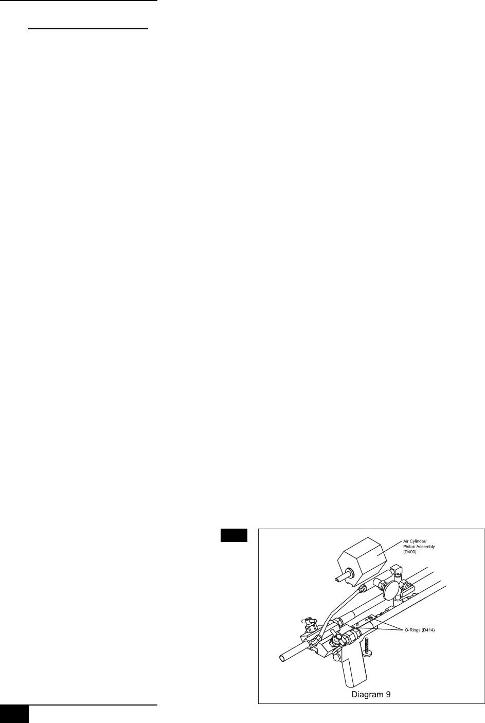
18 | Replace the Cylinder/Handle O Rings (D414) that seal between the Handle
and the Cylinder/Piston Assembly
19 | After ensuring the Mix Cartridge is installed, position the Air Cylinder/
Piston Assembly (D400) on the Handle (D201) so that the appropriate holes in
the bottom line up with the rear alignment pin on the Handle (D201) and that
the Thumbscrew (D413) will easily thread into the bottom of the Air Cylinder/
Piston Assembly (D400). The notch in the Connecting Rod (D405) should fit over
the notch in the small rod sticking out of the Mix Cartridge (D603 or other
optional Mix Cartridge)
(See diagram 36A)(See diagram 36A)
(See diagram 36A)(See diagram 36A)
(See diagram 36A)
20 | Tighten the Thumbscrew (D413)
21 | Realign the Air Injection System by rotating it around back into position,
and re-connect the plastic tubing where it enters the air fitting on the side of
the Mix Cartridge (D603 or other optional Mix Cartridge)
(See diagram 37B)(See diagram 37B)
(See diagram 37B)(See diagram 37B)
(See diagram 37B)
3.1.3
Air Cylinder/ PistonAir Cylinder/ Piston
Air Cylinder/ PistonAir Cylinder/ Piston
Air Cylinder/ Piston
Assembly (D400)Assembly (D400)
Assembly (D400)Assembly (D400)
Assembly (D400)
Diagram 36A
