Installation & Servicing3
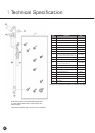
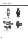
3.1 Cold Water Manifold
This manifold contains a pressure reducing valve (with
integral strainer), double check valve, expansion valve
with a stainless steel seat. The pressure reducing valve is
factory set. The set pressure is shown on top of the
valve. Maximum inlet pressure to valve is 12 bar.
3.2 Installation
1. Cold water supply to be 22mm nominal size.
2. Flush supply pipework before connection to
remove all flux and debris prior to fitting the
inlet controls. Failure to do this may result in
irreparable damage to the controls and will
invalidate the warranty.
3. The manifold can be installed in any position as long
as it is installed in the correct flow direction. Refer to
the arrows on the side of the body.
4. The expansion valve should be either horizontal or
upright - if fitted inverted, debris may be deposited
on the seat and cause fouling of the seat when the
valve operates. Check direction of flow arrows.
5. The black plastic plug in the body is a pressure
gauge connection to enable pressure monitoring to
be carried out, should the system develop a fault. It is
recommended that this be accessible.
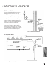
6. Expansion relief drain pipework must be connected
to a safe visible discharge point via a tundish and the
pipework must have a continuous fall.
7. The pressure reducing valve has two outlets, the
second one is for a balanced cold water supply, to a
shower or a bidet (over rim type only, ascending
spray type requires type AA, AB or AD air gap).
Major shower manufacturers advise fitting a
mini expansion vessel in the balanced cold
supply to accommodate thermal expansion and
prevent tightening of shower controls. Do not
use the balanced cold connection to supply
bath taps as this can reduce the flow of water
available to the cylinder. If the balanced cold water
outlet is not required, blank off the port using the
blanking disc supplied (see page 21, fig. 15).
Both the Installation/Guarantee Card and the
Benchmark book enclosed with the cylinder should
be completed after commissioning of the system.
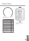
8. The expansion vessel must be fitted to the cold feed
pipe between the pressure reducing valve and the
cylinder. No valve should be fitted between the
expansion vessel and cylinder.
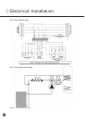
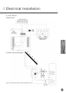
Water Supply
Installation & Servicing
9