TZ-3 TOTALZONE® ZONE CONTROL PANEL
5 68-0223-2
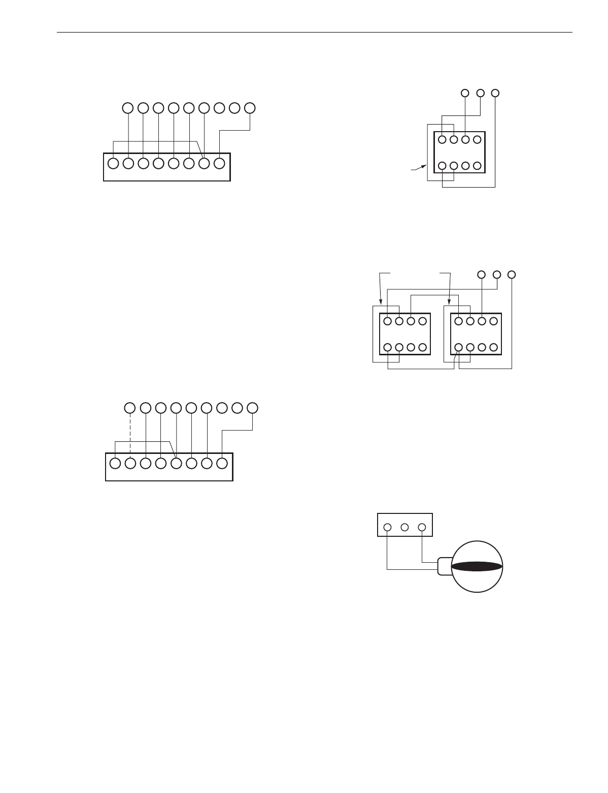
Fig. 4. Heat pump thermostat with separate Y1 and W1
terminals and multi-stage thermostat wiring.
If the thermostat selected has a sin
le Y terminal, see Fi
. 5.
Select a sin
le Y thermostat for each zone. See Table 1.
Set DIP switch 6 or 7
not both
to the On
osition. Set switch
6 to On when B on the thermostat is wired to W on the
anel.
Set switch 7 to On when 0 on the thermostat is wired to W on
the
anel.
When usin
the zone thermostat to control the second sta
e
of heat
W2
, set DIP switch 5 to On, and DIP switch 1 to Off.
Fig. 5. Heat pump thermostat with single Y thermostat
wiring.
Wire the AOBD, AOBD-BM and IOBD Dam
ers to the
anel
as shown in Fi
. 6. See Fi
. 7 when usin
two dam
ers on
one zone. When three or more dam
ers are controlled on
one zone, a slave dam
er control rela
SDCR
is re
uired.
Fig. 6. AOBD single damper wiring.
Fig. 7. AOBD multiple damper wiring.
Wire the ARD or ZD Dam
er to the
anel as shown in Fi
. 8.
Multi
le dam
ers can be wired in
arallel. When ARD or ZD
dam
er is used, the zone LEDs switch directl
from red to
reen
never amber
.
Fig. 8. ARD or ZD Damper wiring.
Wire the MARD or CDO-51 Dam
er to the
anel as shown in
Fi
. 9. These are floatin
control modulatin
dam
ers, but are
controlled as two-
osition dam
ers on the TZ-3
anel.Two
dam
ers can be wired in
arallel.
LW2 G Y R W M6
GLW2E Y1 R W1 C/X
M4 M1
THERMOSTAT
ZONE CONNECTIONS ON PANEL
ZONE THERMOSTAT
M19065
MOTOR
LGYR W M6
E W2 L G Y R O C/X
M4 M1W2
THERMOSTAT
ZONE CONNECTIONS ON PANEL
HEAT PUMP ZONE THERMOSTAT
M19066
MOTOR
4
M6 M4 M1
5 6
123
Z
X
DAMPER MOTOR
FIELD JUMPER
M19067
MOTOR TERMINALS
4
M6 M4 M1
5 6
123
DAMPER MOTORS
M19068
MOTOR TERMINALS
4 5 6
123
Z
X
Z
X
FIELD JUMPER
M6 M4 M1
M19037A
DAMPER TERMINALS
ON PANEL
POWER CLOSE
SPRING OPEN
MODEL ARD, ZDS, ZDB


