34
9) Disconnect the drain hose and reservoir hose from the evaporator.
10) Remove the packing.
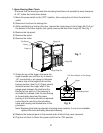
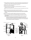
11) Remove the allen head cap screws securing the extruding head and evaporator ange.
Remove the evaporator ange, then grasp the cutter and carefully lift out the cutter and
extruding head. Grasp the top of the auger and carefully lift out the auger. When pulling
out the auger, the upper part of the mechanical seal should come out with it.
12) Remove the evaporator condensate drain pan.
13) Install a temporary tap-line valve on the high side, then recover the refrigerant and store
it in an approved container.
14) Disconnect the inlet and outlet tubing.
15) Remove the allen head cap screws securing the evaporator to the lower housing.
16) Lift off the evaporator.
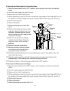
17) Inspect the mechanical seal and O-ring prior to installing the new evaporator. The
mechanical seal consists of two parts. One moves along with the auger, and the other
is xed on the lower housing. If the contact surfaces of these two parts are worn,
cracked or scratched, the mechanical seal may cause water leaks and should be
replaced. Instructions for removing the mechanical seal and lower housing are located
later in this procedure.
18) Make sure the lower mechanical seal and the O-ring are in place, then place the
evaporator assembly in position. Secure the evaporator to the lower housing using the
allen head cap screws.
19) Replace the tap-line valve with a proper, permanent access valve.
20) Remove the drier, then place the new drier in position.
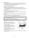
21) Braze all ttings while purging with nitrogen gas owing at a pressure of 3 to 4 PSIG.
22) Use an electronic leak detector or soap bubbles to check for leaks. Add a trace of
refrigerant to the system (if using an electronic leak detector), and then raise the
pressure using nitrogen gas (140 PSIG). DO NOT use R-134a as a mixture with
pressurized air for leak testing.
23) Evacuate the system, and charge it with refrigerant. See the nameplate for the required
refrigerant charge.
24) Reattach and secure the reservoir hose, drain hose, and drain plug.
25) Install the auger assembly with the upper part of the mechanical seal attached. Replace
the cutter, extruding head, and evaporator ange in their correct positions.
26) Open the water supply line shut-off valve and check for water leaks. Replace the
removed parts in the reverse order of which they were removed.
27) Plug the unit back in. Move the power switch to the "ON" position.