555 Dawson Drive, Camarillo, CA 93012 Phone 805-482-6913 • Fax 805-482-7422
4
Rev F
6/08
No.1208-1351
A Division of Thiessen Products, INC
IInnssttrruuccttiioonn SShheeeett FFoorr BBooxx 11 112200”” OOrr 113311””
EEnnggiinnee AAsssseemmbblliieess OOrr EEnnggiinnee RRaaccee KKiittss
BBooxx OOnnee EEnnggiinnee RRaaccee KKiitt
IInnssttaallllaattiioonn IInnssttrruuccttiioonnss
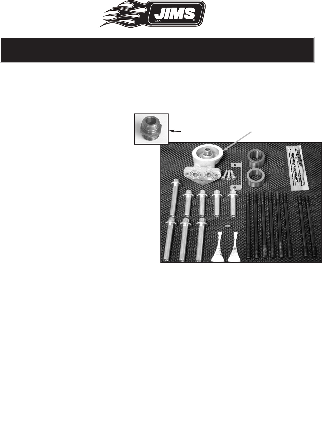
Inspection of parts for box 1
Fig.3 - Box 1 components - See Page 9
Note: Please verify contents of box 1 and complete
inspection of these parts prior to proceeding with
installation as listed on page 9. Please contact
JIMS
®
Tech Support (805-482-6913) if there are
any issues with the parts enclosed. See Fig.3 and
page 4.
Lower End Assembly Inspection
• Read and remove Red Tag attached to the plas-
tic bag containing the lower end.
• Cut open the protective plastic bag, and with
the help of a friend carefully remove the lower
end from the box and place it into your engine
stand.
• Refer to the manufacturer’s instructions included with your engine stand for proper installation.
• Replace the blue foam rod protectors into cylinder spigot bore (prevents rod from knocking in case).
• Remove masking intended for cleanliness as indicated.
• Check case finish for scratches may have resulted from shipping.
• Cover lower end assembly with the supplied clean clear plastic bag
Cylinder Studs
• You will find eight (8) cylinder studs. Two (2) short studs and six (6) long studs.
• Verify presence of green loctite 620 for use when installing the cylinder studs.
Note: Touch-up paint is included in box 2 for your convenience. Please see directions for proper application
and curing.
Fig.3 - Box 1 components - See Pages 9
For “A” Engine, 99-06 FL,
99-05 FXD
Part No. 1286-1346 (Black)
Part No. 1286-1345 (Silver)
For “B” Engine, 06 FXD,
& 07 FL to Pres
Part No. 1486-1835


