CONFIGURING THE SM-PLUS DRIVE
Entering Program Mode:
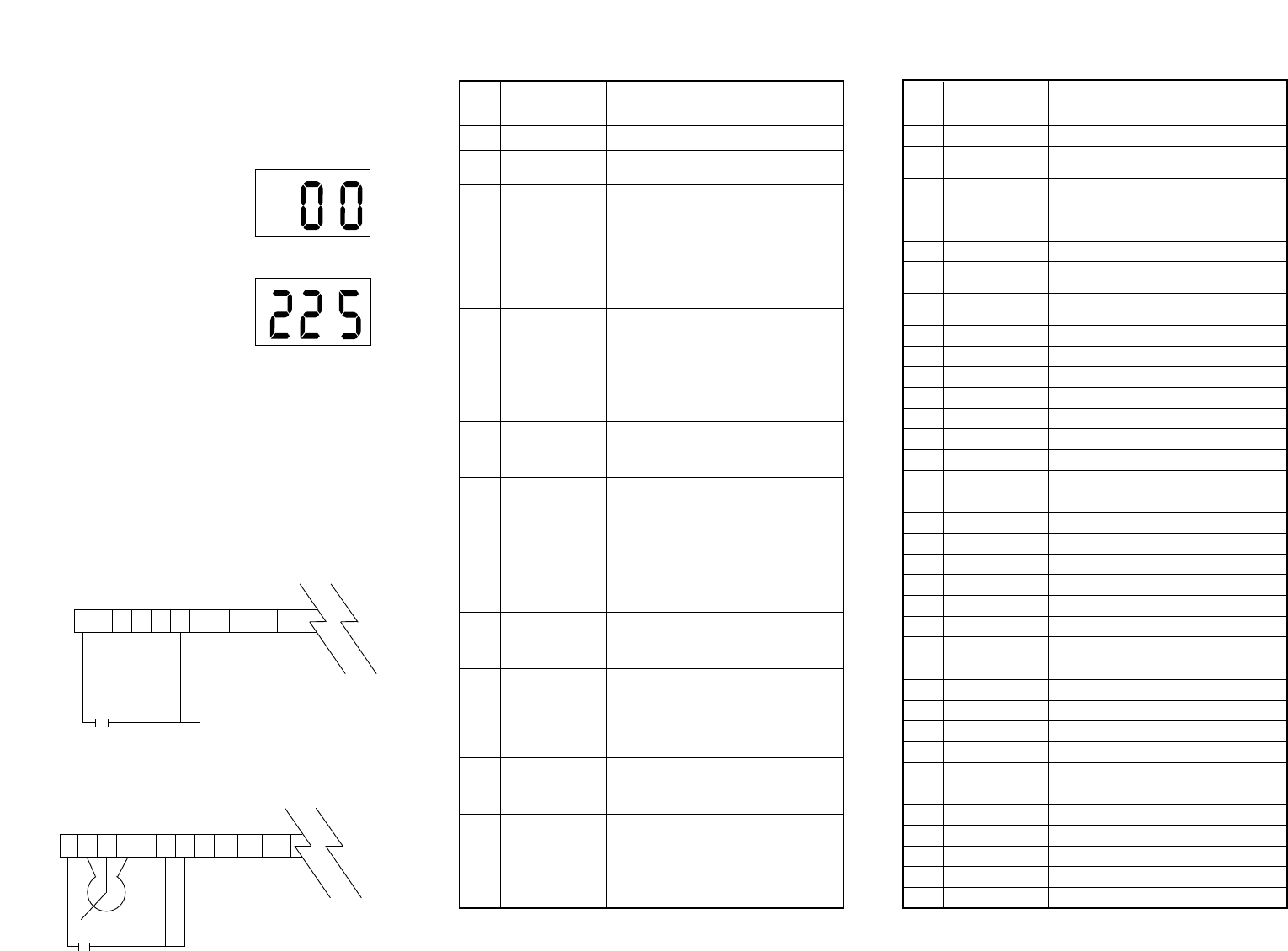
To access the parameters, press the Mode button. This will activate
the password prompt. The display will read “00” and the right-hand
decimal point will be blinking as shown below. Use the and
buttons to scroll to the password value (the factory default password
is 225) and press Mode to enter.
1 2 5 6 11 12 2 14 13A 13B 13C
•
1 2 5 6 11 12 2 14 13A 13B 13C
•
Press Mode
Display reads “00”
Upper right decimal point blinks
°
x
°
x
NO.
Parameter Range of Factory
Name Adjustment Default
01 Line Voltage High (01), Low (02) High (01)
02 Carrier Frequency 6 kHz (02)
03 Start Method Normal (01)
04 Stop Method Coast (01)
05 Speed Source Keypad (01)
06 TB-14 Output None (01)
13 TB-15 Output None (01)
08 TB-30 Analog Out None (01)
09 TB-31 Analog Out None (01)
10 TB-13A Select None (01)
11 TB-13B Select None (01)
12 TB-13C Select None (01)
14 Control
9600, 8, N, 2
15 Serial Link
with Timer (02)
SM-PLUS PARAMETER MENU
4 kHz (01), 6 kHz (02),
8 kHz (03), 10 kHz (04)
Normal (01), Start on Power-up (02),
Start w/DC Brake (03),
Auto Restart w/DC Brake (04),
Flying Restart 1 (05),
Flying Restart 2 (06),
Flying Restart 3 (07)
Coast (01), Coast with
DC Brake (02), Ramp (03),
Ramp with DC Brake (04)
Keypad (01), Preset #1 (02),
0-10 VDC (03), 4-20 mA (04)
None (01), Run (02), Fault (03),
Inverse Fault (04), Fault Lockout (05),
At Set Speed (06),
Above Preset #3 (07),
Current Limit (08), Auto Speed (09),
Reverse (10)
None (01), 0-10 VDC Freq (02),
2-10 VDC Freq (03),
0-10 VDC Load (04),
2-10 VDC Load (05)
None (01), 0-10 VDC Load (02),
2-10 VDC Load (03),
Dynamic Braking (04)
None (01), 0-10 VDC (02),
4-20 mA (03), Preset Speed #2 (04)
Decrease Freq (05), Jog Forward (06),
Jog Reverse (07), Auxiliary Stop (08)
None (01), 0-10 VDC (02),
4-20 mA (03), Preset Speed #1 (04),
Run Reverse (05), Start Reverse (06),
External Fault (07),
Remote Keypad (08), DB Fault (09),
Auxiliary Stop (10),
Accel/Decel #2 (11)
None (01), 0-10 VDC (02),
4-20 mA (03), Preset Speed #3 (04),
Increase Freq (05),
External Fault (06),
Remote Keypad (07),
DB Fault (08),
Accel/Decel #2 (09)
Terminal Strip Only (01),
Remote Keypad Only (02),
Terminal Strip or
Remote Keypad (03)
Disable (01)
9600, 8, N, 2 with Timer (02),
9600, 8, N, 2 , without Timer (03),
9600, 8, E, 1 with Timer (04),
9600, 8, E, 1, without Timer (05)
9600, 8, 0, 1 with Timer (06)
9600, 8, 0, 1 without Timer (07)
NO.
Parameter Range of Factory
Name Adjustment Default
16 Units Editing Tenths of Units (01), Whole Units (02) Whole Units (02)
17 Rotation
19 Acceleration Time 0.1 - 3600.0 sec 20.0 sec
20 Deceleration Time 0.1 - 3600.0 sec 20.0 sec
21 DC Brake Time 0.0 - 3600.0 sec 0.0 sec
22 DC Brake Voltage 0.0 - 30.0% 0.0%
23 0.0 - Maximum Frequency 0.0 Hz
24 Minimum Frequency - 240.0 Hz 60.0 Hz
25 Current Limit 30 - 180% 180%
26 Motor Overload 30 - 100% 100%
27 Base Frequency 25.0 - 500.0 Hz 60.0 Hz
28 Fixed Boost 0.0 - 30.0% 1.0%
29 Accel Boost 0.0 - 20.0% 0.0%
30 Slip Compensation 0.0 - 5.0% 0.0%
31-37 Preset Speeds 0.0 - Maximum Frequency 0.0 Hz
38 Skip Bandwidth 0.0 - 10.0 Hz 0.0 Hz
39 Speed Scaling 0.0 - 6500.0 0.0
40 Frequency Scaling 3.0 - 2000.0 Hz 60.0 Hz
41 Load Scaling 10 - 200% 200%
42 Accel/Decel #2 0.1 - 3600.0 sec 20.0 sec
43 Serial Address 1 - 247 1
44 Password 000-999 225
47 Clear History Maintain (01), Clear (02) Maintain (01)
User Settings (01),
48 Program Selection OEM Settings (02), Reset OEM (03),
Reset 60 (04), Reset 50 (05)
50 Fault History View Only (N/A)
51 Software Code View Only (N/A)
52 DC Bus Voltage View Only (N/A)
53 Motor Voltage View Only (N/A)
54 Load View Only (N/A)
55 0-10 VDC Input View Only (N/A)
56 4-20 mA Input View Only (N/A)
57 TB Strip Status View Only (N/A)
58 Keypad Status View Only (N/A)
59 TB-30 Output View Only (N/A)
60 TB-31 Output View Only (N/A)
Maximum
Frequency
Minimum
Frequency
User Settings
(01)
Run/Stop
Contact
Speed Pot
Run/Stop
Contact
•
To add a potentiometer for speed control, change Parameter #5
(Standard Speed Source) to 0-10 VDC (03).
Once the PROGRAM mode is accessed, use the and buttons
to scroll to the desired parameter number, and press the Mode
button to see the parameter setting. Use the and buttons to
change the parameter setting and press Mode to store the new
setting.
Connections:
Below is a sample wiring diagram for two-wire start/stop control.
The drive is ready to use right out of the box, with these simple con-
trol wiring connections; no parameter adjustments are required.
Speed is controlled from the and buttons on the front of the
drive.
°
Use and to scroll to the password
value (factory default password is 225)
Press Mode to enter password
°
Forward Only (01),
Forward and Reverse (02)
Forward Only
(01)
Terminal Strip
(01)