Page 32
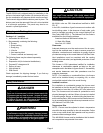
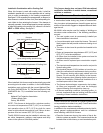
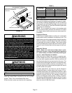
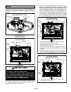
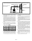
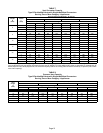
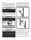
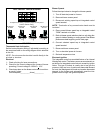
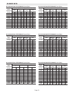
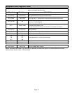
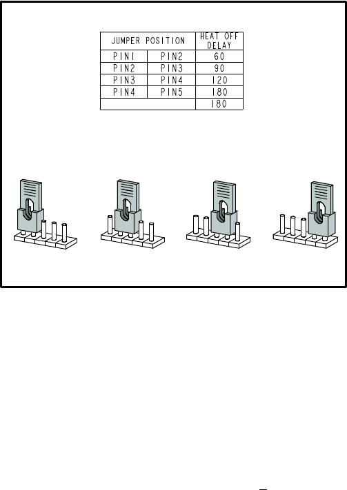
HEAT FAN-OFF TIME IN SECONDS
To adjust fan−off timing, reposition jumper across pins to
achieve desired setting.
NO JUMPER
FIGURE 36
60
90
120
180
60
90
120
180
60
90
120
180
60
90
120
180
60 Second
off Time
90 Second
off Time
120 Second
off Time
180 Second
off Time
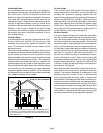
Thermostat Heat Anticipation
Set the heat anticipator setting (if adjustable) according to
the amp draw listed on the wiring diagram that is attached
to the unit.
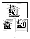
NOTE − Do not secure the electrical conduit directly to the
air ducts or structure.
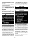
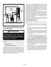
Electrical
1 − Check all wiring for loose connections.
2 − Check for the correct voltage at the furnace (furnace
operating). Correct voltage is 120VAC + 10%.
3 − Check amp−draw on the blower motor with inner blow-
er panel in place.
Unit Nameplate__________Actual__________
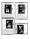
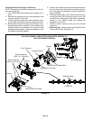
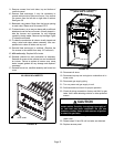
Blower Speeds
Follow the steps below to change the blower speeds.
1 − Turn off electrical power to furnace.
2 − Remove blower access panel.
3 − Disconnect existing speed tap at integrated control
speed terminal.
NOTE − Termination of any unused motor leads must be
insulated.
4 − Place unused blower speed tap on integrated control
PARK" terminal or insulate.
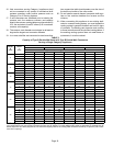
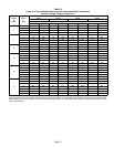
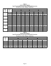
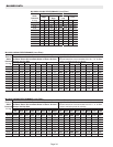
5 − Refer to blower speed selection chart on unit wiring dia-
gram for desired heating or cooling speed. See Blower
performance data beginning on the next page.
6 − Connect selected speed tap at integrated control
speed terminal.
7 − Resecure blower access panel.
8 − Turn on electrical power to furnace.
9 − Recheck temperature rise.
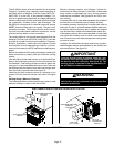
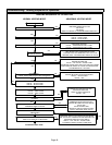
Electronic Ignition
The integrated control has an added feature of an internal
Watchguard control. The feature serves as an automatic re-
set device for integrated control lockout caused by ignition
failure. This type of lockout is usually due to low gas line
pressure. After one hour of continuous thermostat demand
for heat, the Watchguard will break and remake thermostat
demand to the furnace and automatically reset the inte-
grated control to begin the ignition sequence.