OFF
MARK BLOWER
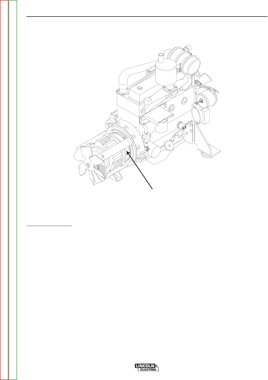
PADDLE HERE
FIGURE F.6 – STROBE MARK LOCATION
ENGINE THROTTLE ADJUSTMENT TEST PROCEDURE (CONTINUED)
PROCEDURE
Strobe-tach Method
1. Conduct this procedure with the engine OFF.
2. Unlatch, lift and secure the right side engine ser-
vice access door. Perform the Case Cover
Removal and Replacement Procedure. (For
Strobe-Tach method only.)
3. With a white or red marking pencil, place a mark on
one of the blower paddles. See Figure F.6 for loca-
tion.
4. Connect the strobe-tach according to the manufac-
turer's instructions.
5. Start the engine and direct the strobe-tach light on
the blower. Synchronize it to the rotating mark.
With the machine at HIGH IDLE the tach should
read between 1890 and 1910 RPM.
With the machine at LOW IDLE the tach should
read between 1450 and 1500 RPM. (Cummins
1425).
6. If either of the readings is incorrect, adjust the
throttle as follows:
Adjust HIGH IDLE: Use the 10mm wrench to
loosen the locking nut. See Figure F.7 for location
of the adjusting screw and locking nut. Turn the
threaded screw counter-clockwise to increase the
HIGH IDLE speed. Adjust the speed until the tach
reads between 1890 and 1910 RPM. Retighten
the locking nut.
Adjust LOW IDLE: First make sure there is no load
on the machine. Set the IDLE switch to AUTO and
wait for the engine to change to low idle speed.
Use the 10mm wrench to loosen the solenoid lever
arm locking nut. See Figure F.7. Adjust the collar,
to change the amount of throw in the lever arm,
until the tach reads between 1450 and 1500 RPM.
Retighten the locking nut.
TROUBLESHOOTING AND REPAIR
F-26 F-26
VANTAGE® 500
Return to Section TOC Return to Section TOC Return to Section TOC Return to Section TOC
Return to Master TOC Return to Master TOC Return to Master TOC Return to Master TOC


