MODEL 110 AUTORANGING DIGITAL MULTIMETER
7
5.2 DC Voltage Measurements
WARNING
Maximum Input Voltage is 600VDC. To avoid electrical shock hazard and/or
damage to this instrument, do not attempt to make any voltage measurement that
may exceed this limit.
1. Connect the red test lead to the
‘V’
jack
and the black test lead to the
‘COM’
jack.
2. Set the Function Selector switch to the
V range.
3. Connect the test leads in parallel with
the circuit being measured.
4. Read the measured voltage on the
instrument display.
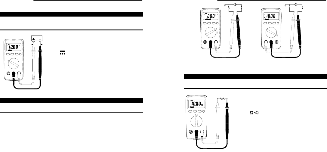
5.3 AC/DC Current Measurements
WARNING
To avoid injury, do not attempt a current measurement if the open circuit voltage
exceeds the rated voltage of the meter.
1. If the current to be measured is unknown, connect the red test
lead to the
‘A’
jack. If it is known or has been determined that
the current is 400mA or less, connect the red lead to the
‘µA/mA’
jack. Connect the black test lead to the
‘COM’
jack.
2. Set the Function Selector switch to the current range
corresponding to the jack being used and press the blue
button to select AC or DC.
3. Remove power from the circuit to be measured and connect
the instrument in series with this circuit. Connect the black
lead to the negative (-) side and the red lead on the positive (+)
side being measured.
4. Apply power to the circuit and read the measured current on
the instrument display.
MODEL 110 AUTORANGING DIGITAL MULTIMETER
8
uA or mA measurement Amp measurement
5.4 Resistance Measurements
WARNING
Before making any in-circuit measurements, remove power from the circuit being
tested and discharge all capacitors in the circuit.
1. Connect the red test lead the to
‘
:
’
jack
and the black test lead to the
‘COM’
jack.
2. Set the Function Selector switch to
the range and press the blue
button to select the
:
function.
3. Remove power from the circuit being
tested and discharge all capacitors in
the circuit.
4. Connect the test leads in parallel with
the circuit to be measured and read the
measured resistance on the instrument
display.


