TYPICAL APPLICATIONS
DIMENSIONS
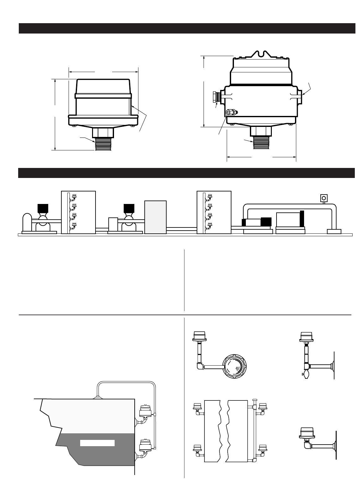
Typical Water Flood Control System
The diagram above displays eight DF Series switches installed on a
Raw Water tank and a Clear Water tank. When raw water rises to
predetermined level, DF#1 stops the supply pump. As tank level
falls below the predetermined level, DF#2 starts the supply pump. If
the tank level continues to fall, DF#3 initiates shutdown of the sup-
ply pump. DF#4 stops transfer pump before raw water tank is com-
pletely pumped out.
When clear water reaches the predetermined level, DF#5 stops the
transfer pump. As tank level falls to predetermined low level, DF#6
starts the transfer pump. If the tank level continues to fall due to the
failure of the filters section, DF#7 initiates shutdown of the transfer
pump. (DF755 located at this level will also operate backwash
equipment). DF#8 stops injection pump before tank pumps com-
pletely out.
An OPL Series pressure SWICHGAGE
®
stops injection pump when
pressure reaches predetermined high or low pressure.
Tank with Low Pressure
Gas Blanket (DF755EX)
The DF755EX (below) is shown installed on a crude oil tank where
a low pressure gas blanket is used to prevent evaporation loss. It is
mounted directly to the side of the tank or on riser pipe 4 to 7 in.
(102 to 178 mm) below level to be controlled. Pump automatically
stops or starts when liquid reaches predetermined high or low level.