8
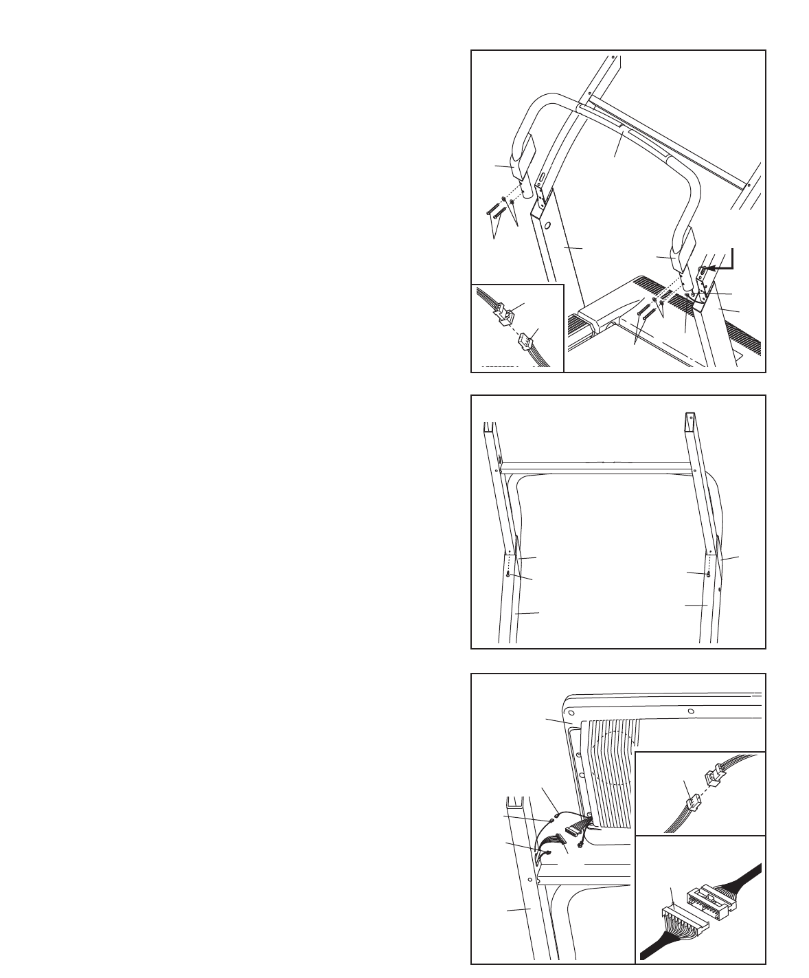
6. Press the two Upright Covers (75) onto the Upright Base
(85). Attach each Upright Cover with a 3/4” Screw (7).
85
75
7
85
75
7
6
7. Cut the tie securing the Wires to the Upright Base (85).
Have a second person hold the console assembly near the
Upright Base (85). Connect the Upright Wire Harness (73)
and the Pulse Wire (74) to the wires extending from the
console assembly. The connectors should slide together
easily and snap into place. If they do not, turn one con-
nector and try again. Insert the connectors into the
Console Assembly. If necessary, remove the right acces-
sory tray (not shown) from the console assembly.
Connect the Upright Ground Wire (113) to the ground wire
extending from the console assembly. Make sure that the
wires are fully inserted into each other. Insert the ground
wires into the Console Assembly. Reinsert the right acces-
sory tray (not shown) into the console assembly if neces-
sary.
85
73
Console
Assembly
Ground
Wire
74
113
7
73
74
5. Slide the two Upright Covers (75) onto the ends of the
Pulse Bar (69). Align the holes in the lower ends of the
P
ulse Bar with the holes in the Upright Base (85).
C
ut the tie securing the Pulse Wire (74) to the Upright
Base (85). Do not cut the indicated black tie. Connect
the Pulse Wire to the Pulse Bar Wire (79). The connec-
tors should slide together easily and snap into place.
If they do not, turn one connector and try again. Insert
the wires down into the right side of the Upright Base.
Hold the Pulse Bar (69) against the Upright Base (85).
Do not drop the Pulse Bar into the Upright Base. Attach
the Pulse Bar to the Upright Base with the four Pulse Bar
Bolts (66) and four Star Washers (67).
Be careful not to
pinch the wires. Start all four Pulse Bar Bolts before
tightening them.
Slide the Upright Covers (75) over the Pulse Bar Bolts
(66).
85
85
75
69
74
79
66
67
66
75
5
67
79
74
Do Not
Cut
