36
Regency Bellavista™ B36X Gas Fireplace
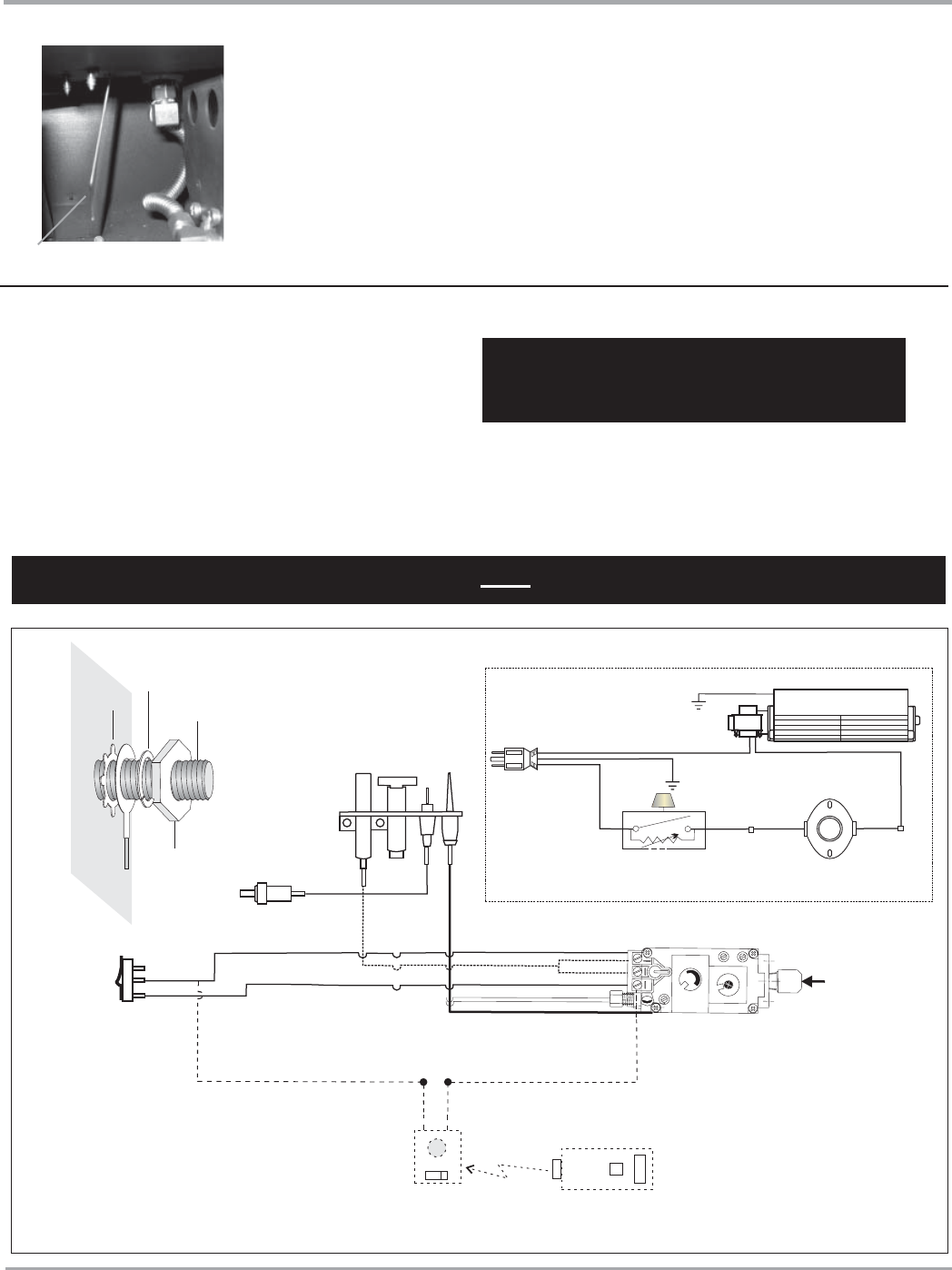
WIRING DIAGRAM
AERATION ADJUSTMENT
The burner aeration is factory set but may need
adjusting due to either the local gas supply or
altitude. Open the air shutter for a blue fl ame or
close for a more yellow fl ame.
Minimum Air Shutter Opening:
NG 1/16"
LP 1/4"
CAUTION: Label all wires prior to disconnection
when servicing controls. Wiring errors can cause
improper and dangerous operation.
Caution: Ensure that the wires do not touch any
hot surfaces and are away from sharp edges.
CAUTION: Carbon will be produced if air shutter
is tightly closed.
Note: Any damage due to carboning
resulting from improperly setting
the aeration controls is NOT covered
under warranty.
INSTALLATION
This heater does not require a 120V A.C. supply for operation. In case of a power failure, the burner switch and the optional remote control/ther-
mostat will continue to operate. However, a 120V A.C. power supply is needed for the fan/blower operation.
(Do not cut the ground terminal off under any circumstances.)
NOTE: Even if the fan is not purchased with the unit, it is still a good idea to bring power to the receptacle box (provided with the unit) in case the
fan is installed at a later date.
Ground
Green
Neutral
Live
Black Red Red
Minimum Convection
Air Temp. Switch
Ground
ON OFF
Rotary Speed
Control
120V AC
60 Hz
Fan
Piezo
Ignitor
To Thermocouple IN
Pilot
Assembly
H
I
L
O
O
F
F
O
N
P
I
L
O
T
Gas Pilot
Thermopile
Thermocouple
Electrode
Lockwasher
Fan
ground wire
Nut
#8 Ground Lug
(mobile home
approved)
Star washer
Remote Transmitter
(Optional)
ON OFF
Regency
Remote Receiver
or Thermostat
(Millivolt) (Optional)
Brown
White
Black
White
"S.I.T" Valve
Burner
ON
OFF
(To THTP)
(To TH)
(To TH)
White
Gas
In
Optional Fan # 576-917
For NATURAL GAS Units and Units NOT Equipped with DC Spark Boxes
Air shutter rod - located to the left
of the valve assembly.


