930-110-01-B.00 PowerLogic
TM
EM4800 Series
04/2011 Installation
© 2010 Schneider Electric All Rights Reserved
21
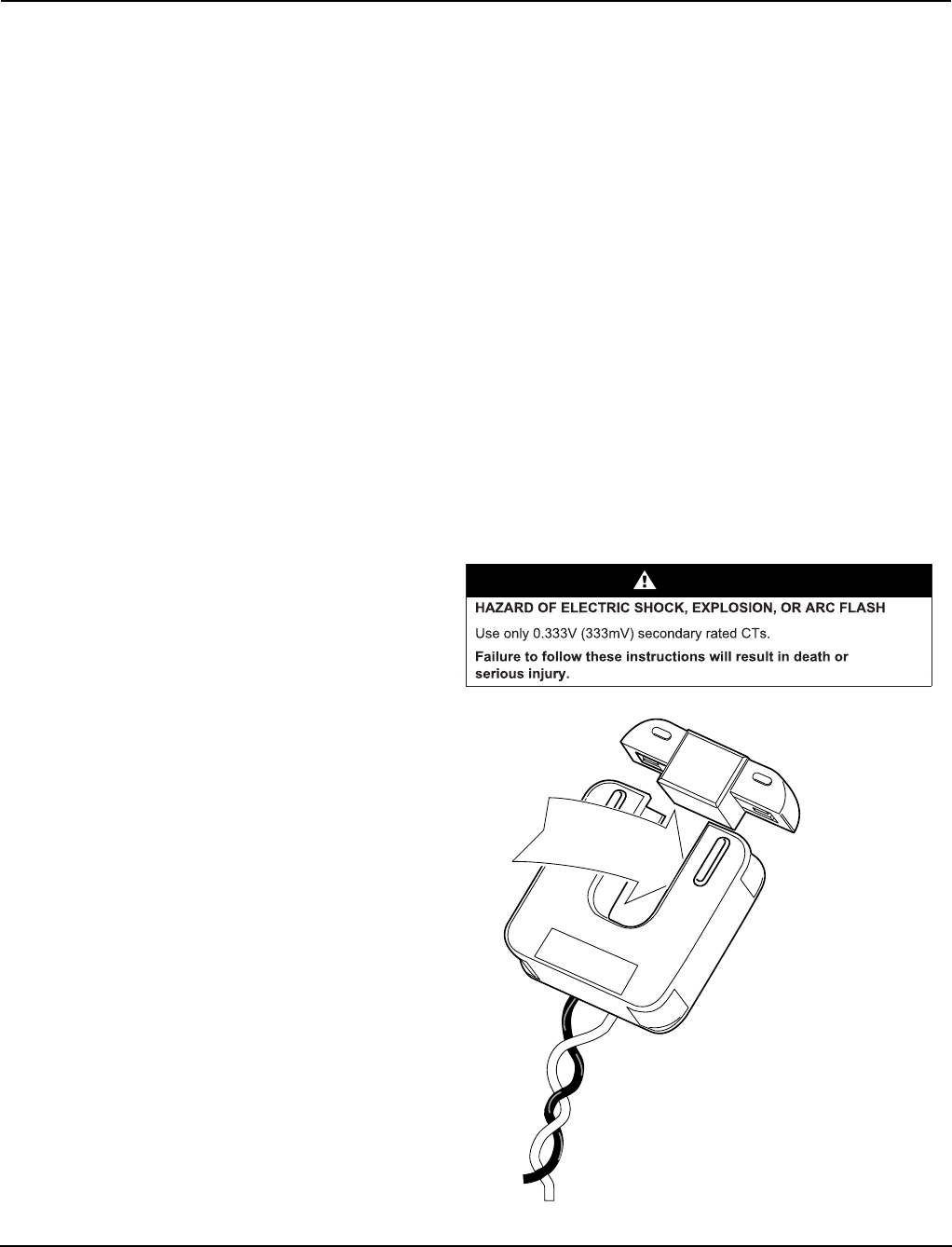
Installing the Current Transformers The three models of PowerLogic EM4800 meter use current transformers
(CTs) with different secondary outputs. The PowerLogic EM4833 meter uses
split-core 0.333V CTs (see Figure 12), and the PowerLogic EM4880 meter
uses 80mA CTs only (see Figure 13) and is typically used where accuracy is
important and long secondary CT wiring is required (up to 300 feet [91.44
meters]). The PowerLogic EM4880 meter can also use a 5A CT if a 5A
converter has first been installed.
For instructions, see “Installing the CTs on the PowerLogic EM4833 and
PowerLogic EM4880” on page 22, and “Installing 5A Converters and CTs on
the PowerLogic EM4880” on page 23.
The PowerLogic EM4805 uses 5A secondary CTs. For instructions, see
“Installing the 5A CTs on the PowerLogic EM4805” on page 27.
Current transformers connect to the PowerLogic EM4833 and PowerLogic
EM4880 meters through the 50-conductor CT cable provided with the meter.
Table 2 describes the CT wire pairs and the cable color scheme for each
meter point. You can also find this information on the inside of the meter’s
outer cover.
Each CT has an X1 (positive) and X2 (neutral) wire pair and uses butt-splice
connectors to attach the CT to a specific meter wire pair. The direction of the
energy flow is indicated on the CT.
Figure 12: PowerLogic EM4833 split-core 0.333V current transformer
3
1
2
T
H
ISSID
ET
OWARDS S
O
UR
C
E
4
5
Legend:
1 Source
2 Energy ow
3 Load
4 X1
5 X2
DANGER


