90
Chaper 4 Operation Tips
Chapter 4 Operation Tips
Setting
• Connect AD 1 to 24 to CH-1 to CH-24.
• When the DMBK-R105 is inserted in the option slot, connect each input channel of the
DMBK-R105 to Insertion return 1 to 8.
• When the DMBK-R101/103/104/106/107 is/are inserted, connect them starting from the
lowest slot number to the channels from CH-25 in order.
Monaural
0 dB
0 Frame, COARSE: OFF
Control: Center, Button: ON
Front center
100 %
OFF
PGM L/R: ON
Control : Center, Button: OFF
Control :Center, Button: OFF, EXPANDER: Access
Set all busses to monaural, OFF and POST
Set all groups to GANG and OFF.
OFF
- infinity
• Connect PGM L/R busses to the PGM L/R connectors.
• Connect the AUX 1 to 8 busses to the AUX 1 to 8 connectors.
• When the DMBK-R105 is inserted in the option slot, connect each output channel of the
DMBK-R105 to insertion send 1 to 8.
• When the DMBK-R102/103/106/107 is/are inserted.
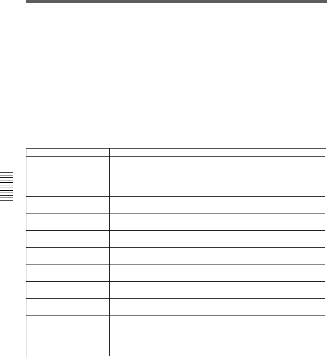
Item
Input routing
Channel mode
Trim setting of the input signal
Delay amount
Pan, MTR pan
Surround pan
Divergence
MTR assign
PGM assign
Equalizer
Dynamics
AUX send
Fader group
Cut
Fader
Output routing
Memory Structure and Title
When you use the unit for first time (with the default setting) or
there are no current files
Create the current title with the following settings for the synchronous
signal and timecode mode:
For detailed information on how to set these items, see “SYNC/TIME CODE
Window” on page 76.
• Sampling frequency: 48 kHz
• Sync-lock (reference synchronous signal): INTERNAL
• Timecode mode: NTSC30NDF
Create the initial cue and snapshot with the following settings:
• Initial cue: 00:00:00:01
• Snapshot: not linked.
Default setting of the unit


