Toshiba
–20–
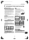
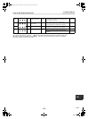
4-way Air Discharge Cassette Type
Installation Manual
EN
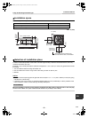
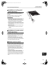
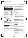
Wire connection
REQUIREMENT
• Be sure to connect the wires matching the terminal numbers. Incorrect connection causes a trouble.
• The low-voltage circuit is provided for the remote control. (Do not connect the high-voltage circuit)
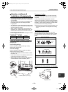
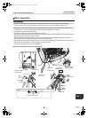
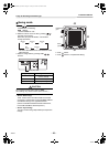
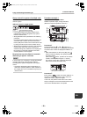
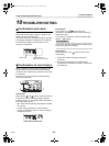
• Remove the cover of the electric parts box by taking off the mounting screws (2 positions) and pushing the
hooking section. (The cover of the electric parts box remains hanged to the hinge.)
• Remove the 2 screws from the wire cover.
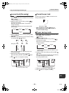
• Attach the conduit pipe to the conduit plate with a lock nut.
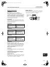
• Connect the system interconnection wires and remote control wire to the terminal block of the electric parts box.
Secure the ground wire with the ground screw.
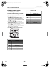
• Tighten the screws of the terminal block, and fix the wires with cord clamp attached to the electric parts box.
(Do not apply tension to the connecting section of the terminal block.)
• Mount the wire cover without catching the wires. (The wire cover should be mounted before the ceiling panel.)
• Mount the cover of the electric parts box without catching the wires.
(Mount the cover after wiring on the ceiling panel.)
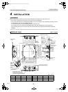
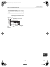
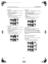
▼ Thermal insulation to wiring connecting port
A
B
L1 L2 S
Hinge
Electric parts
box cover
Wire cover
Screws at 2 positions
Louver connector
(CN510: White)
Power supply
terminal block
Conduit
connection hole
Piping
Knockout
Hole for remote
control wires
Lock nut
Conduit pipe
Conduit plate
Remote
control
terminal block
Cord clamp
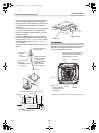
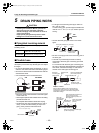
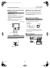
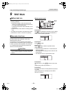
Side D
(Space: 0.33” (8.5 mm))
Side C
(Space: 0.16” (4 mm))
Insert the wire to Side C.
Ground screw
20-EN
+00EH99864701_00Ta.book Page 20 Tuesday, November 24, 2009 4:54 PM