TABLE OF CONTENTS
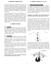
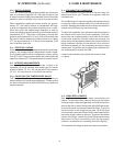
The serial tag is a permanently afxed sticker on
which is recorded vital electrical and refrigeration
data about your Traulsen product, as well as the
model and serial number. This tag is located in
the upper right interior compartment on all reach-
in/pass-thru and roll-in/roll-thru refrigerator, freezer
and dual-temp models. For hot food models, this tag
is located on the top of the unit behind the louvers to
protect it from the heat.
I. THE SERIAL TAG
-1-
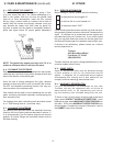
READING THE SERIAL TAG
• Serial = The permanent ID# of your Traulsen
• Model = The model # of your Traulsen
• Volts = Voltage
• Hz = Cycle
• PH = Phase
• Total Current = Maximum amp draw
• Minimum Circuit = Minimum circuit ampacity
• Lights = Light wattage
• Heaters = Heater amperage (Hot Food units only)
• Refrigerant = Refrigerant type used
• Design Pressure = High & low side operating
pressures and refrigerant charge
• Agency Labels = Designates agency listings
SERIAL MODEL
VOLTS Hz PH
TOTAL CURRENT AMPS
MINIMUM CIRCUIT AMPS
MAXIMUM OVERCURRENT PROTECTION AMPS
LIGHTS WATTS
HEATERS AMPS
REFRIGERANT TYPE OZ
DESIGN PRESSURE HIGH LOW
REFRIGERANT TYPE OZ
DESIGN PRESSURE HIGH LOW
FORT WORTH, TX.
370-60294-00 REV (A)
I. THE SERIAL TAG Page 1
II. RECEIPT INSPECTION Page 2
III. INSTALLATION
a-Location Page 2
b-Packaging Page 2
c-Installing Legs or Casters Page 2
d-Tray Slides Page 3
e-Cord & Plug Page 3
f-Power Supply Page 3
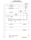
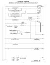
g-Wiring Diagram Page 3
h-Clearance Page 3
IV. OPERATION
a-Even-Thaw Overview Page 3
b-Expected Performance Page 3
c-Even-Thaw Operation Page 3
d-Batch Loading Page 4
e-Process Loading Page 4
f-Interior Arrangements Page 4
g-Adjusting The Temperature Scale Page 4
h-Operator Controls, Blower Switch Page 4
i-Call Service Light Page 4
V. CARE & MAINTENANCE
a-Cleaning The Condenser Page 4
b-Hinge Replacement Page 4
c-Replacing The Gaskets Page 5
d-Cleaning The Exterior Page 5
e-Cleaning The Interior Page 5
VI. OTHER
a-Service Information Page 5
b-Spare Parts Page 5
c-Warranty Registration Page 5
VII. GEN’L USE, OPERATION & SERVICE Page 6
VIII. EXPECTED THAW PERFORMANCE/
OPERATIONAL TROUBLESHOOTING
a-Introduction Page 6
b-Test Parameters Page 6
c-Test Results Page 6
d-Results as a Function of Product Mix Page 6
e-Incomplete Thawing Page 7
f-Equipment Issues Page 7
g-Causes Of Extended Thaw Times Page 7
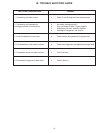
IX. TROUBLE SHOOTING GUIDE Page 8
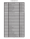
X. SPARE PARTS LIST Page 9
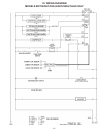
XI. WIRING DIAGRAMS Page 10-12
XII. WARRANTY INFORMATION Page 13