VGZ-029 / 20110519.0 TR009 PERFORMER™ / Page 9
CONNECTOR PIPE INSTALLATION
Connector pipe is used to make the connection
from the final positioning of your stove to an approved
chimney. Connector pipe is NOT included as part of the
stove. Connector pipe must be 6” diameter minimum of
24 MSG (minimum standard gauge) black or 26 MSG
blue steel stove pipe. Connector pipe is not rated to
provide close contact to combustible materials and
must have proper clearance from combustible materials
as shown in the clearance diagrams on the previous
pages. Connector pipe should never be used in place
of a chimney. If proper clearances are not observed a
house fire could result.
INSTALLATION INSTRUCTIONS
1. The crimped end of the stovepipe fits inside the
stove flue collar. Secure with three (3) sheet metal
screws. The first section of connector pipe must be
single walled to properly attach to the stove collar.
Install additional pipe and elbow with the crimped
end towards the stove. This will allow any conden-
sation in the flue to run back into the firebox.
2. Horizontal pipe runs must slope upwards
towards the chimney at least 1/4” per foot of hori-
zontal run.
3. You must have at least 18 inches of clearance
between any horizontal piping and the ceiling.
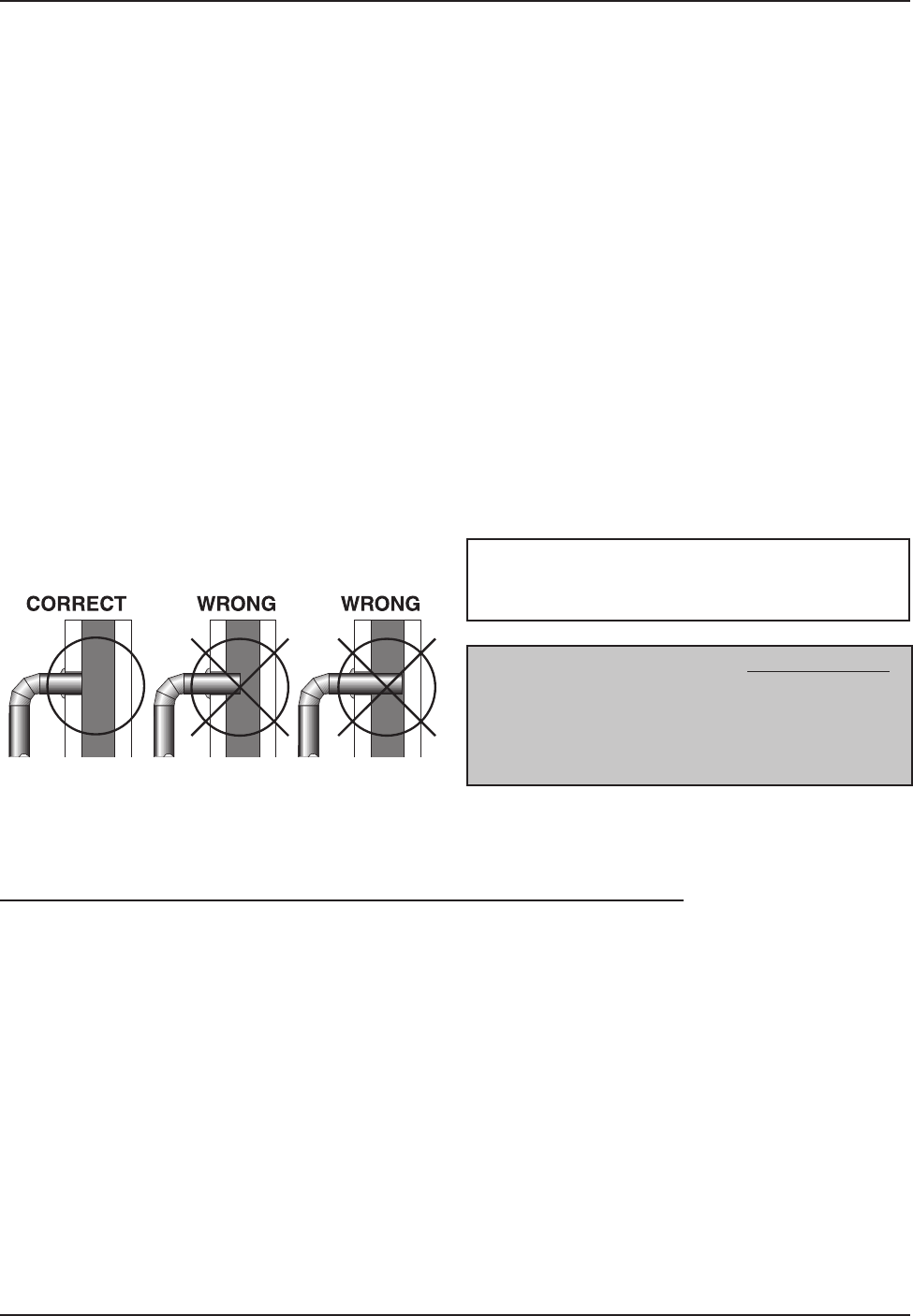
4. The pipe cannot extend into the chimney flue
(figure 14).
5. Secure pipe/elbow sections with three (3) sheet
metal screws at each joint to make the piping
rigid.
6. It is recommended that no more than two (2)
90° bends be used in the stovepipe installa-
tion. The use of more than two 90° bends may
decrease the amount of draw and possibly
cause smoke spillage. Where possible, use only
corrugated (non adjustable) elbows. These
provide a better seal.
7. The connector pipe must not pass through an
attic or roof space, closet, or any concealed space,
floor, ceiling, wall, or combustible construction. (See
Chimney Connector Systems & Clearances, page
22.) A UL 103 HT Listed chimney must be used
from the first penetration of ceiling or wall to the
chimney cap.
CAUTION: NEVER USE SINGLE WALL CON-
NECTOR PIPE AS A CHIMNEY - A HOUSE FIRE
COULD RESULT.
Figure 14 – Stovepipe/Flue Connections
NOTE: CONNECTOR PIPE IS NOT INCLUDED.
TO PURCHASE, VISIT YOUR LOCAL HARD-
WARE, HOME, OR BUILDING CENTER.
ADDITIONAL SPECIFICATIONS.
CHIMNEY SIZING
Today’s solid fuel heating appliances are much
more efficient than those made in the past. Your heat-
ing appliance has been designed to provide the most
efficient transfer of heat possible from the least amount
of fuel.
Controlled combustion is the key to optimum heat-
ing performance. Controlled combustion requires a flow
of fresh air into the appliance, across the fuel and is
finally exhausted up the chimney.
Today’s high efficiency stoves transfer more heat
into the living area and less up the chimney. Exhaust
gases are typically at a lower temperature than tradi-
tional type stoves. With lower exhaust temperatures, it
is important that the chimney is correctly sized to the
stove. If the chimney diameter is too large, it will be dif-
ficult to raise the chimney flue temperature to provide for
adequate draft. This may result in a poor burn, smoke
spillage, and rapid creosote creation. A 6” diameter
chimney is best suited for this stove.
Your heating appliance must have a minimum of
a 6” diameter (152mm) chimney. Maximum chimney
diameter must not exceed 10” (254mm) or have a cross
sectional area greater than 85 sq. in. (550cm
2
.)
Proper draft for this heating appliance is minimum of
0.05 w.c. (water column measurement) and is required
to prevent back puffing, smoke spillage and prevent
safety hazards.


