


5
Cable choice consists mainly of selecting the correct cross sectional area in relation
to the cable length and the load impedance. A small cross sectional area would
increase the cables series resistance, inducing power loss and response variations
(damping factor).
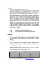
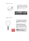
Connectors should be wired with a minimum of 2.5 sq. mm (12 gauge) cable. This will
be perfectly satisfactory under normal conditions. In the case of very long cable runs
the wire size should exceed this, refer to the following table for guidance: -
CABLE RUN
(m)
C.S.A. OF EACH
CONDUCTOR (mm)
CABLE
RESISTANCE Ω
% POWER LOSS
INTO 8Ω LOAD
% POWER LOSS
INTO 4Ω LOAD
10 2.5
4.0
6.0
0.14
0.09
0.06
1.7
1.1
0.73
3.5
2.2
1.5
25 2.5
4.0
6.0
0.35
0.22
0.14
4.3
2.7
1.8
8.6
5.4
3.6
50 2.5
4.0
6.0
0.69
0.43
0.29
8.6
5.4
3.6
17.0
11.0
7.2
100 2.5
4.0
6.0
1.38
0.86
0.58
17.0
11.0
7.2
35.0
22.0
14.0
4. Amplification & Power Handling
As with all professional loudspeaker systems, the power handling is a function of
voice coil thermal capacity. Care should be taken to avoid running the amplifier into
clip (clipping is the end result of overdriving any amplifier). Damage to the
loudspeaker will be sustained if the amplifier is driven into clip for any extended
period of time. Headroom of at least 3dB should be allowed. When evaluating an
amplifier, it is important to take into account its behaviour under low impedance load
conditions. A loudspeaker system is highly reactive and with transient signals it can
require more current than the nominal impedance would indicate.
Generally, a higher power amplifier running free of distortion will do less damage to
the loudspeaker than a lower power amplifier continually clipping. It is also worth
remembering that a high powered amplifier running at less than 90% of output power
generally sounds a lot better than a lower power amplifier running at 100%. An
amplifier with insufficient drive capability will not allow the full performance of the
loudspeaker to be realised.
It is important when using different manufacturers amplifiers in a single installation
that they have very closely matched gains, the variation should be less than +/-
0.5dB. This precaution is important to the overall system balance when only a single
compressor/limiter or active crossover is being used with multiple cabinets; it is
therefore recommended that the same amplifiers be used throughout.
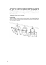
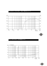
5. Operation
For optimal performance, the iQ 10 has been designed to operate in conjunction with
the Tannoy TDX1 & TDX2 System Controllers, and iQ 18B bass unit for extended
bass performance. The TDX controllers have been factory preset to provide the
recommended eq, crossover points, and overall system balance. Please refer to the
TDX1 & TDX2 manual for operation.
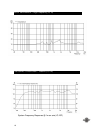
If you intend using an alternative loudspeaker management system (e.g. BSS™,
KlarkTeknik™, XTA™ etc) please refer to section 12 of this manual.