14 7
Connection to the gas supply
Ensure that the gas type at the installation site is the
same as that stated on the appliance rating plate.
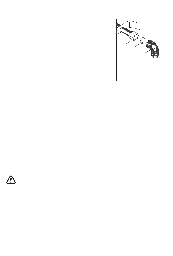
On the end of the shaft, which includes the GJ 1/2”
threaded elbow, adjustment is fixed so that the washer
is fitted between the components as shown in the
diagram. Screw the parts together without using excessive
force.
A) End of gas shaft with nut
B) Washer
C) Elbow
A
B
C
Connection
Connection to the gas supply should be with either rigid or semi-rigid pipe, i.e. steel
or copper.
The connection should be suitable for connecting to RC 1/2 (1/2 BSP male thread).
When the final connection has been made, it is essential that a thorough leak test is
carried out on the hob and installation using leak detection fluid.
Ensure that the main connection pipe does not exert any stain on the hob.
It is important to install the elbow correctly, with the shoulder on the end of the
thread, fitted to the hob connecting pipe.
Failure to ensure the correct assembly will cause leakage of gas.
When cooking with fats or oils, do not leave the pan unattenced because
these substances may catch fire if brought to high temperatures.
Lighting the burners
To obtain a flame more easily, light the burner before placing a cooking utensil
on the pan stand.
To light a burner, proceed as follows: for version with lighting integrated in the
control knob, push the knob of the burner fully down and turn it anticlockwise
to the "maximum flow" setting symbol, or press the button if the appliance has
individual lighting.
After lighting the flame, keep the knob pressed for about 10 seconds; this time
is necessary to heat up the "thermocouple" (Fig. 1-C) and activate the safety
valve, which would otherwise cut off the gas flow.
Then check that the flame is even and turn the control knob to adjust the
flame as required.
In the instance of a power cut, place a flame near the burner and proceed as already
described.
If the flame does not light after a few attempts, check that the "burner cap" and "flame
cap" are correctly positioned.
To turn off the flame, turn the control knob clockwise to the symbol.
Before removing pans from the burners, always lower or turn off the flame.
Correct use of the hob
For lower gas consumption and
to ensure maximum burner effi-
ciency, you should only use pots
and pans with a flat bottom fitting
the size of the burner used (see
table). Also, as soon as a liquid
comes to the boil take care to turn
the flame down to a level that will
just keep it boiling.
Burner minimum maximum
diameter diameter
Large (rapid) 180 mm. 220 mm.
Medium (semi-rapid) 120 mm. 200 mm.
Small (Auxiliary) 80 mm. 160 mm.
Triple Flame 220 mm. 260 mm.
If the control knobs become difficult to turn, please contact your local
Service Force Centre.


