


green and yellow
(earth)
blue (neutral)
brown (live)
fuse
(3amp)
3A
6 15
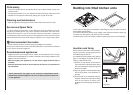
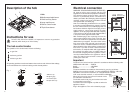
Description of the hob
1.Hob
2.Medium semi-rapid burner
3.Small auxiliary burner
4.Large rapid burner
5.Burner control knobs
6.Triple flame burner
2
5
3
6
2
4
1
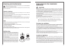
Instructions for use
B
A
C
A
B
C
D
Fig. 1
A-Burner cap
B-Lighting plug
C- Thermocouple
D-Triple flame cap
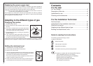
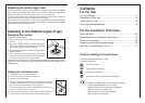
The hob control knobs
The symbols on the control knobs mean the following:
no gas flow
maximum gas flow
minimum gas flow
All operating positions must be set between the maximum and minimum flow settings,
and never between the maximum setting and the closed position.
Once the hob has been installed, it is important to remove any protective
materials, which were put on in the factory.
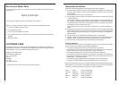
Important
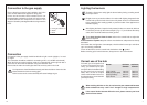
The wires in the mains lead are coloured in accordance with the following code:
GREEN AND YELLOW........EARTH
BLUE....................................NEUTRAL
BROWN ...............................LIVE
The wires should be connected into the terminal of your plug as follows:
EARTH: to the terminal marked E, or coloured GREEN or GREEN / YELLOW.
NEUTRAL: to the terminal marked N, or coloured BLACK or BLUE.
LIVE: to the terminal marked L, or coloured RED or BROWN.
When wiring the plug ensure that all strands of wire
are retained in each terminal.
The flexible mains lead, plug and socket must not be
in contact with hot surfaces.
The lead must not be trapped or pulled aut when the
appliance is fitted.
Plug in the appliance. Turn on the electricity supply.
Electrical connection
WARNING: THIS APPLIANCE MUST BE EARTHED.
All external wiring must comply with the IEE
Regulations for the Electrical Equipment of Buildings.
The electrical supply can be by either a plug and
socket or a permanently wired connection via a
double - pole switch. Should the plug (where supplied)
not fit the socket in your home, it should be removed
and replaced with a suitable plug.
Note: If a moulded plug is fitted which is not suitable,
it must be cut off and disposed of properly. To avoid
the risk of electrocution, the moulded plug must not
be left where children might find it and plug it into a
supply socket. It must not be used for any other
appliance. Three pin plugs to BS1363 with a capacity
of not less than 13A must be used and fitted with a
3 amp fuse ‘ASTA’ approved to BS 1362.
With moulded plugs, after replacing the fuse the
cover must be refitted. If the cover is lost, the plug
must not be used until a replacement cover has been
obtained from your supplier. The colour of the correct
fuse cover is that of the coloured insert in the base
of the fuse recess, or stated elsewhere on the plug.
Always state this colour when ordering a replacement
fuse cover. If you wish to make a direct connection
to the mains, an omnipolar switch with a gap between
the contacts of at least 3 mm, of suitable rating for
the load and complying with the regulations in force,
must be installed between the appliance and the
mains.The switch must not break a contact in the
yellow/green earth wire.
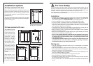
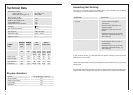
NO
REAR VIEW
YES
COPPER PIPE OR
STAINLESS STEEL HOSE
Service
opening in
cabinet
REAR VIEW
BAND
CLAMPS