


66
NOTE:
THE OPERATIONS INDICATED BELOW MUST
BE FOLLOWED BY QUALIFIED PERSONNEL
EXCLUSIVELY, IN CONFORMITY WITH THE
REGULATIONS IN FORCE.
THE MANUFACTURING FIRM REFUSES ALL
RESPONSIBILITY FOR DAMAGES TO PEOPLE,
ANIMALS OR OBJECTS, RESULTING FROM
THE FAILURE TO COMPLY WITH SUCH
PROVISIONS.
The appliance is designed to be embedded into
heat-resistant cabinetry.
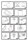
Cut a hole in the top of the cabinetry, with the
dimensions indicated in fig. 3, at a distance of
at least 50 mm from the appliance border to the
adjacent walls.
WARNING:
The surrounding cabinetry must resist a minimum
temperature of 75°C.
The equipment must not be installed near
inflammable materials, such as curtains, cloths,
etc.
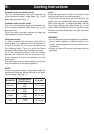
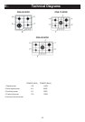
( Ref to Fig. 3 on page 8)
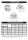
MODEL L (mm) P (mm)
600-750 560 490
900 820 490
If the are any over-head cabinets above the
cooktop they must be a minimum of 762 mm (30")
higher. The distance on the left and on the right
side from lateral wall should be at least 110 mm
(4.5”), while the distance from the back wall should
be at least 25 mm (1”).
It is advisable to isolate the appliance from the
piece of furniture below with a separator, leaving a
depression space of at least 10 mm (fig. 4).
If the hob is going to be installed above an oven,
precautions must be taken to guarantee installation
is in accordance with current accident prevention
standards. Pay particular attention to the position
of the electric cable and gas pipe: they must not
touch any hot parts of the oven.
WARNING:
If the hob is going to be installed on the top of a
built in oven without forced cooling ventilation,
proper air vents must be installed to guarantee an
adequate ventilation, with the lower air entering
–
–
with a cross section of at least 200cm
2
, and the
higher air exiting with a cross section of at least
60 cm
2
.
Fastening the top
Every cook-top is equipped with a special washer
and a set of hooks for mounting the cook-top.
Once the cut-out is made in the cabinet surface,
the installation procedure is as follows:
Remove the trivets and complete burners from
the top.
Turn the appliance upside down and lay the ‘S’
washer along the external border (fig. 5).
Place the cook-top in the hole made in the piece
of furniture then block it with the V screws of the
fastening hooks G (fig. 6 / 6A).
NOTE:
This appliance is not provided with a device for
exhausting the products of combustion.
Please check your local regulations to ensure
installation is in conformity.
Gas Connection
Make sure that the appliance is adjusted for the
gas type available in your area (see the label under
the appliance). Follow the instructions indicated in
the chapter “gas transformations and adjustments”
for the possible adaptation to different gases.
The appliance must be connected to the gas
system by means of still metal pipes or flexible
steel pipes having continuous walls, in compliance
with the regulations in force in your area. Some
models are equipped with cylindrical A and conical
B connectors for gas supply (fig. 7).
WARNING:
The connection must not stress the gas ramp.
Electric connection
The connection to the electric grid must be carried
out by qualified personnel and in conformity with
the regulations in force in your area.
The voltage of the electric system must correspond
to the value indicated in the label under the
appliance. Make sure that the electric system is
provided with an effective ground connection in
compliance with the regulations and provisions of
the law.
Grounding is compulsory.
–
–
–
D - Installation & Warnings