


64
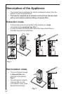
Installation
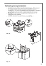
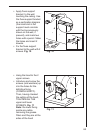
• Remove the grease filters.
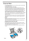
• Drawing a line on the wall with a pencil up to the ceiling,
corresponding to the centre line, will make the installation
operations easier. Fig. 7
• Apply the perforation diagram to the wall: the vertical centre line
printed on the perforation diagram should correspond to the centre
line drawn on the wall. In addition, the lower edge of the perforation
diagram corresponds to the lower edge of the hood. Fig. 8
= =
Fig. 7
Fig. 8
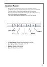
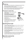
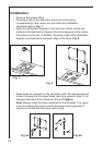
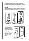
• Make holes as indicated on the template, insert the wall dowels and
screw 2 screws into the upper holes, leaving a space of about 1 cm
between the head of the screw and the wall. Fig9a-b
Note: Always make the holes indicated on the template. The upper
2 are for hooking the hood up while the lower holes (generally 2
lateral) are for the definitive and safety fixing.
Ø 8
Ø 8
5x45
Ø 8
Fig. 9a Fig. 9b