


Protect PV.500-MH Operating Instructions
44 of 68 80000043212 BAL
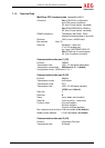
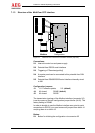
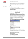
7.1.3 Structure of the MultiCom CCC Interface
1
1
1
1
1
1
1
1
X3
X1
X2
X4
X5
J1
J5
J4
LED
gn
rt
S1
RS232:RS485:
B A B A
Modbus Configuration
Figure 13 MultiCom CCC interface as a Modbus interface (top view)
Connections:
X1: Internal inverter bus and power supply
X2: Potential-free RS232 serial interface
X3: Triggering of "Remote signalling"
X4: A remote panel can be connected to this potential-free CAN
interface.
X5: Potential-free RS485/RS232 serial interface internally wired
to X91
Configuration jumpers:
J1: 1-2: Firmware update; 2-3: (default)
J4: All closed: RS485 (default)
J5: All closed: RS232
The transmission topology of the Modbus interface (connector X5)
is set by means of the two configuration jumper blocks (J4/J5). The
factory setting is RS485.
In order to be able to use the Modbus interface as a point-to-point
connection via RS232, you must remove all jumpers from block J4
and plug them in on block J5.
Button:
S1: Button for initiating the configuration via connector X2