


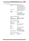
Protect PV.500_MH Operating Instructions
80000043212 BAL 47 of 68
The X5 interface can be switched from RS485 to RS232 using
jumpers J4 and J5. The factory setting is RS485, i.e. all jumpers
are inserted at J4. You have the option of switching the interface to
RS232 by reconnecting all jumpers to J5.
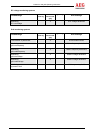
Port 2 (X5): RS232 pin assignment
Pin number Signal Description
2 RxD PC receiving data
3 TxD PC sending data
5 GND Interface reference potential
7 RTS Handshake
8 CTS Handshake
Housing INV housing potential
If the RS232 version is used for this port, please use a 1:1 data
line.
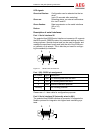
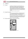
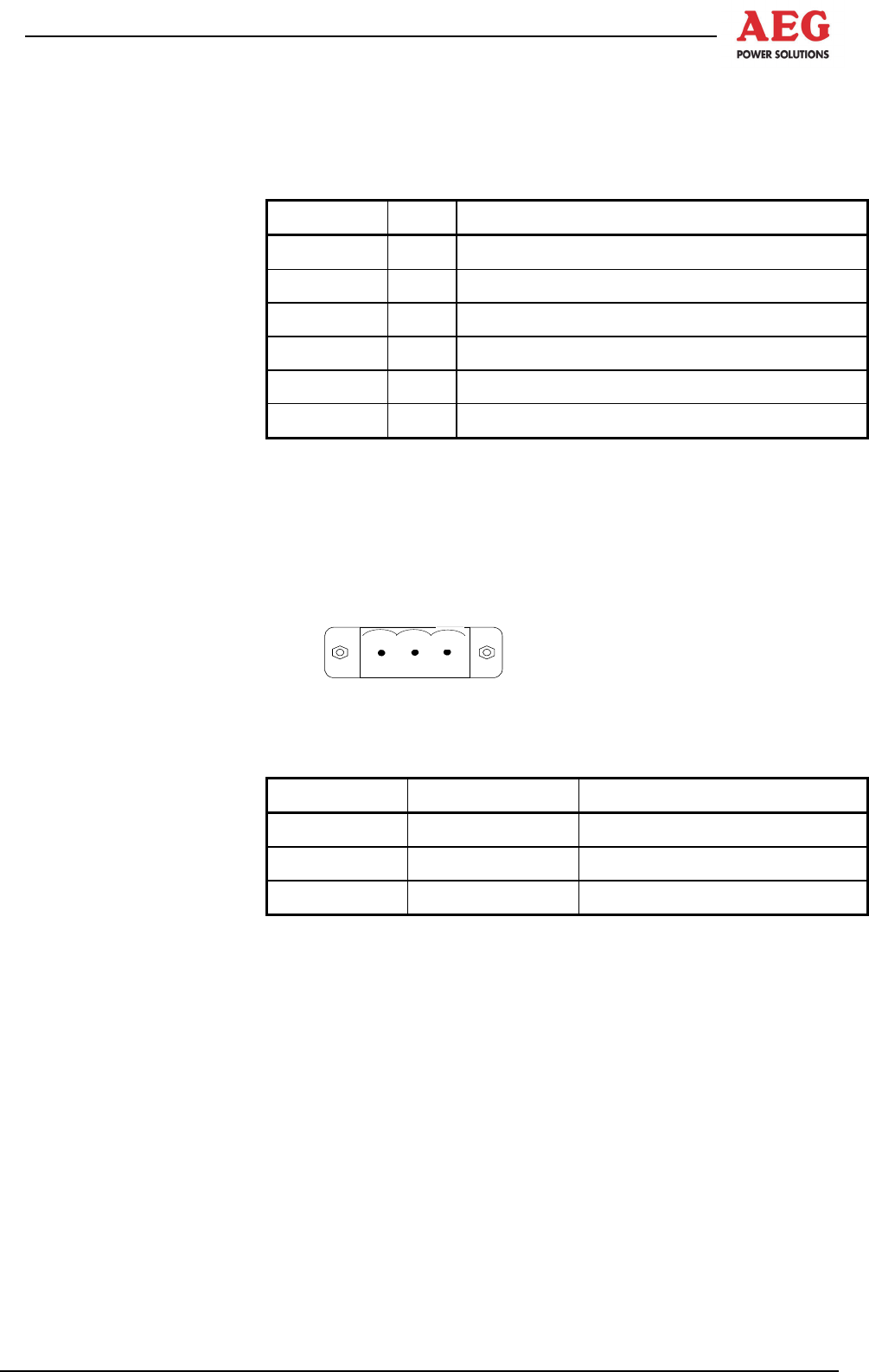
Controller Area Network (CAN) at X4
Up to four remote panels can also be connected to the potential-
free CAN interface for central signalling and display.
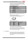
1
Figure 16 Connector X4
Port 3 (X4): CAN pin assignment
Pin number Designation Cable colour coding
1 GND White + brown
2 Data_L Yellow
3 Data_H Green
Please use a shielded CAN bus cable as the line,
e.g. 2 x 0.22 twisted pair Lapp "UNITRONIC-BUS LD".
Route the CAN bus line from the PV inverter to the remote panel.
In a CAN bus network, the ends of the bus must always be termi-
nated. A 120 ohm terminating resistor is pre-installed at connector
X4 of the CAN bus connection as standard.
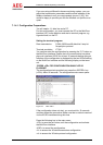
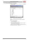
7.1.4 Configuration
The communication interface does not have to be configured in or-
der to connect the PV inverter to the data logger system of the
AEG "PV.LoG". Once the bus cable has been installed and the
system has been powered up, the configuration settings are made
fully automatically.