www.airkinglimited.com
5S7635037 New 10-06 5 of 16
CAUTION: ALL ELECTRICAL CONNECTIONS MUST BE MADE
IN ACCORDANCE WITH LOCAL CODES, ORDINANCES, OR
NATIONAL ELECTRICAL CODE. IF YOU ARE UNFAMILIAR WITH
METHODS OF INSTALLING ELECTRICAL WIRING, SECURE THE
SERVICES OF A QUALIFIED ELECTRICIAN.
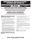
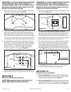
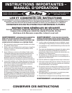
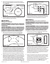
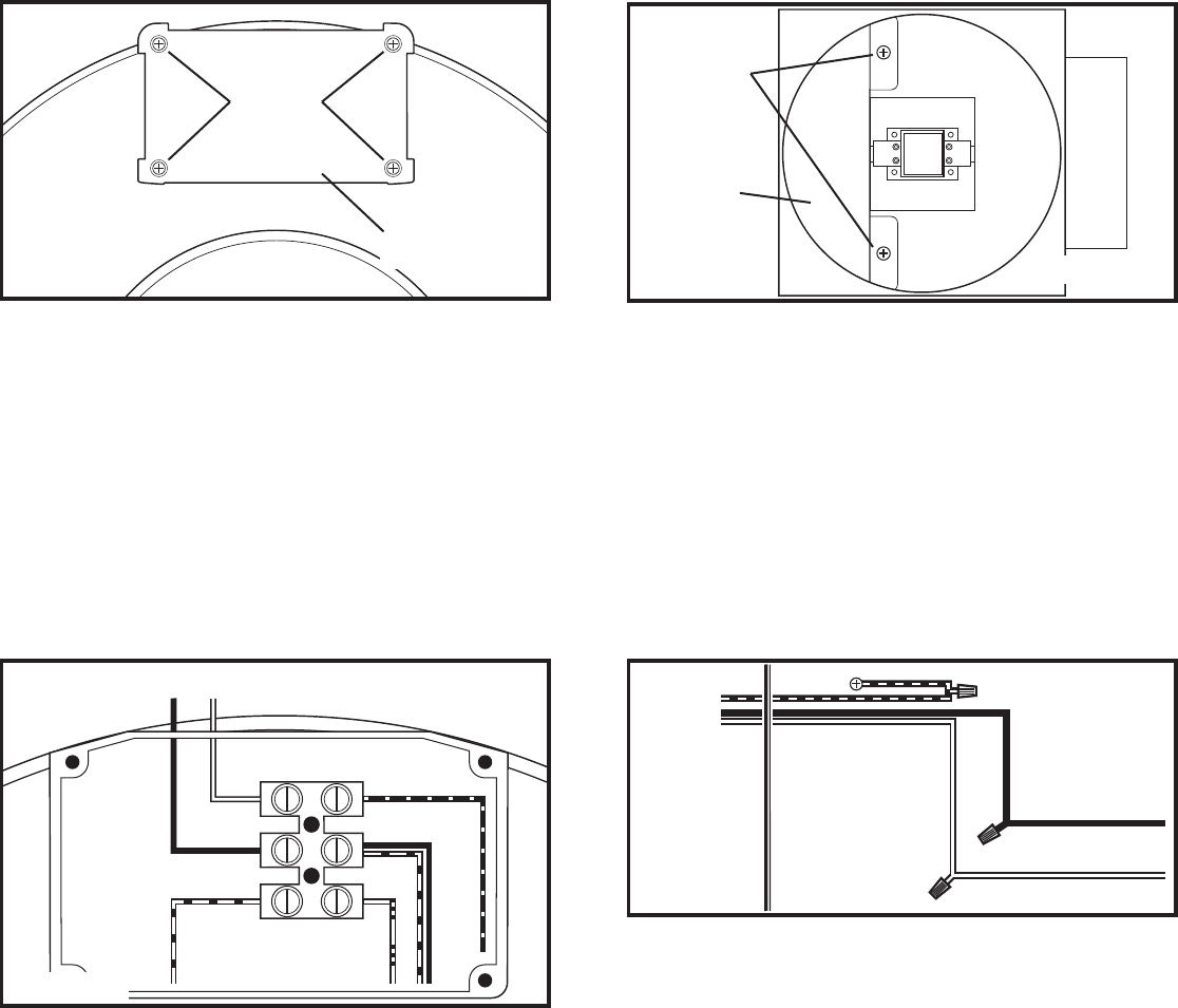
1. Remove the screws securing the terminal box cover plate
located on the side of the motor
(Figure 13).
2. Run wiring from an approved wall switch carrying the
appropriate rating. One neutral (white) and one hot (black
lead connected to the switch). Secure the electrical wires
to the housing with an approved electrical connector. Make
sure you leave enough wiring in the terminal box to make the
connections to the fan’s pre-wired electrical terminal strip.
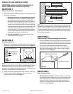
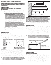
3. Insert the white wire from the house into the terminal strip
port labeled “N” and tighten using a small regular screwdriver.
Insert the black wire from the wall switch into the terminal
strip port labeled “L” and tighten using a small regular
screwdriver. Since the motor is isolated within a plastic
housing, grounding is not necessary
(Figure 14).
4. Check to make sure all wire connections are securely fastened
to the terminal strip and replace the fan terminal box cover.
SECTION 9
Wiring the Ceiling Grill Housing
CAUTION: MAKE SURE POWER IS SWITCHED OFF AT
SERVICE PANEL BEFORE STARTING INSTALLATION.
Supply from house
Blue
Black/Red
Brown
Red
Black
White
N
L
Figure 14
CAUTION: ALL ELECTRICAL CONNECTIONS MUST BE MADE
IN ACCORDANCE WITH LOCAL CODES, ORDINANCES, OR
NATIONAL ELECTRICAL CODE. IF YOU ARE UNFAMILIAR WITH
METHODS OF INSTALLING ELECTRICAL WIRING, SECURE THE
SERVICES OF A QUALIFIED ELECTRICIAN.
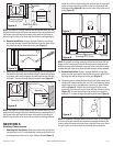
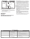
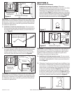
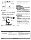
1. Remove the screws inside the housing securing the electrical
cover in place
(Figure 15).
2. Run wiring from an approved wall switch carrying the
appropriate rating. One neutral (white) and one hot (black lead
connected to the switch). Secure the electrical wires to the
housing with an approved electrical connector. Make sure you
leave enough wiring in the terminal box to make the connections
to the housing’s pre-wired electrical terminal strip.
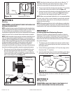
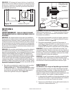
3. From where you have access to inside the housing’s junction
box, connect the white wire from the house to the white wire
from the light socket. Connect the black wire from the wall
switch to the black wire from the light socket. Connect the
ground wire from the house to the green wire from the grounding
screw (Figure 16). Use approved methods for all connections.
4. Re-install the electrical cover, making sure all wires are
tucked inside the box and are not being pinched.
SECTION 10
Completing the Installation
1a. Halogen Light Models: Install the included halogen lamp by
gently inserting into the socket and turning the lamp until it
is properly seated within the socket
(Figure 17).
1b. Fluorescent Light Models: Install the included 4 pin fluorescent
lamp by gently inserting into the socket and pushing inward
until the lamp is properly seated within the socket
(Figure 17).
Screws
Housing
Figure 15
Cover
Figure 13
Screws
Terminal Box
Figure 16
Ground
Supply
from
house
White
Hot (Black)