


www.airkinglimited.com
5S7635036 New 9-06 3 of 12
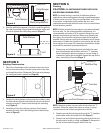
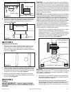
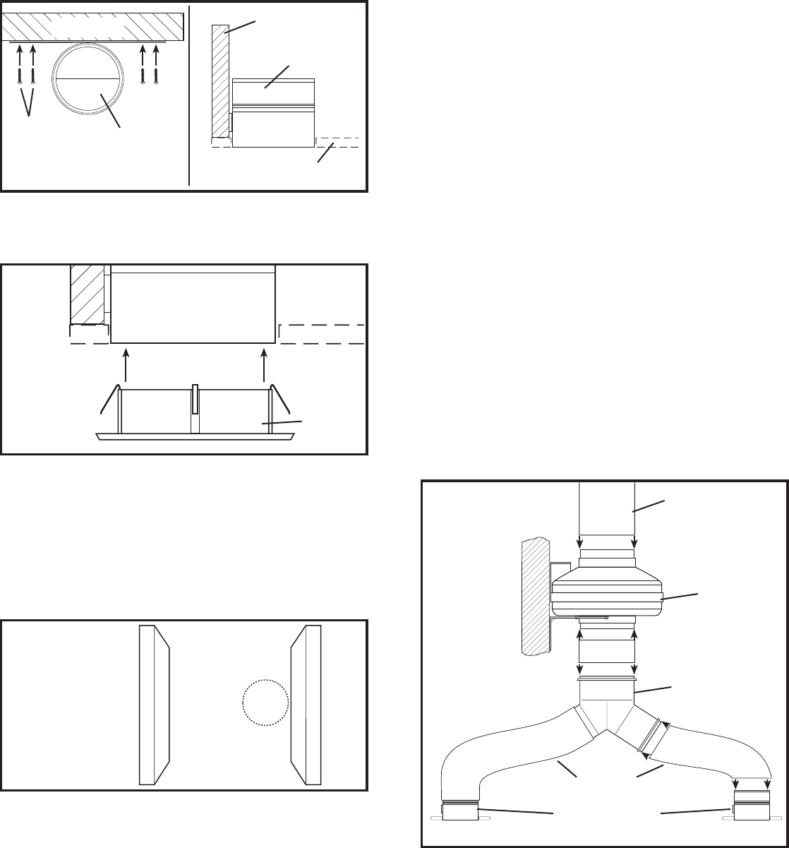
2. Once the wall/ceiling material is in place, install the grill into
the collar by pushing it firmly inward towards the collar until
it fits flush against the wall/ceiling material
(Figure 5).
SECTION 5
Existing Construction
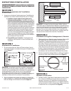
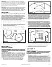
1. Place the collar/damper in the selected location and trace
a circle onto the surface. From the interior side of the room,
cut through the surface. Please note: Take care not to damage
the ceiling and make a smooth cut (Figure 6).
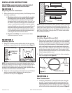
2. Position the collar/damper in the previously cut hole so that
it is flush with the finished ceiling and secure to the joist/stud
using the provided 1" wood screws through the mounting
strap (Figure 4).
3. Install the grill
into the collar by pushing it firmly inward
towards the collar until it fits flush against the wall/ceiling
material
(Figure 5).
SECTION 6
Ducting
CAUTION: ALL DUCTING MUST COMPLY WITH LOCAL
AND NATIONAL BUILDING CODES.
NOTE: Insulated ducting is required for bathroom exhaust
applications, where ducting passes through unconditioned space
or where noise is a factor. Failure to use insulation could result
in excessive condensation buildup within the duct, and
undesirable sound levels within the room. Duct runs should have
as few bends as possible.
NOTE: Flexible insulated ducting may be used where allowed
by local code. For the quietest possible installations, it is
recommended a minimum of 8' of insulated flexduct be used
between any exhaust grill and fan. When using flexible type
duct work, duct should be stretched as tight and straight as
possible. Failure to do so could result in dramatic loss of system
performance. Flexible duct should be connected to the fan with
screw clamps or duct tape. All connections should be as airtight
as possible to maximize system performance.
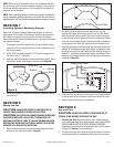
1. Connect one end of the ducting (not included) to the room
level collar/damper and the other end to the “Y” transition.
Secure both ends in place using tape or a screw clamp to
create as air tight a seal as possible. Repeat this step for the
other room level grill housing (Figure 7).
NOTE: Units that include only one collar do not utilize the “Y”
transition. Follow the same instructions as in step 1, except
connect the one end of the ducting directly to the fan.
2. Connect one end of the ducting to the top of the “Y” transition
and the other end to the intake of the fan (Figure 7).
3. Connect one end of the ducting to the exhaust of the fan and
the other end to a wall or ceiling cap (Figure 7). Always duct
the fan to the outside through a wall or roof cap.
Figure 6
Exhaust to
Wall/Roof Cap
Fan
“Y” Transition
Collar/Damper
Ducting
Figure 4
Collar/Damper
Wall/Ceiling Material
Joist/Stud
Collar/Damper
Screws
Joist/Stud
Grill
Figure 5
Collar/Damper
Figure 7