


www.airkinglimited.com
5S7635036 New 9-06 4 of 12
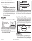
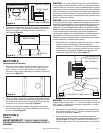
NOTE: When using insulated flex duct, it is recommended that
the inner vinyl core be screw clamped or taped to the inlet and
outlet and that the vapor barrier surrounding the insulation be
taped to the fan housing.
NOTE: When attaching flex duct to the collar/damper combination
and an immediate elbow is necessary, be certain that the elbow is
installed with a "soft" bend to allow damper blades to operate properly.
SECTION 7
Installing Optional Balancing Damper
Some kits include an optional balancing damper to allow for
adjustment of the system. The damper may be used where the
grills will be connected using branches of unequal length or
where the flow will need to be balanced for any reason. To Install
the optional damper:
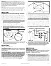
1. The damper must be installed on the branch with the least
restriction. This is generally the duct that is shortest or has
the fewest bends.
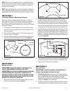
2. Drill a 5/16" hole approximately 1-1/2" from the edge on the
flat side of the “Y” transition.
3. Insert the shaft of the damper into the hole drilled in step 2. Place
the washer, handle, then wing nut onto the shaft (Figure 8).
4. Adjust the damper to balance airflow and tighten the wing
nut to secure.
SECTION 8
Wiring the Fan
CAUTION: MAKE SURE POWER IS SWITCHED OFF AT
SERVICE PANEL BEFORE STARTING INSTALLATION.
CAUTION: ALL ELECTRICAL CONNECTIONS MUST BE MADE
IN ACCORDANCE WITH LOCAL CODES, ORDINANCES, OR
NATIONAL ELECTRICAL CODE. IF YOU ARE UNFAMILIAR WITH
METHODS OF INSTALLING ELECTRICAL WIRING, SECURE THE
SERVICES OF A QUALIFIED ELECTRICIAN.
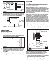
1. Remove the screws securing the terminal box cover plate
located on the side of the motor
(Figure 9).
2. Run wiring from an approved wall switch carrying the
appropriate rating. One neutral (white) and one hot (black
lead connected to the switch). Secure the electrical wires
to the housing with an approved electrical connector. Make
sure you leave enough wiring in the terminal box to make the
connections to the fan’s pre-wired electrical terminal strip.
3. Insert the white wire from the house into the terminal strip port
labeled “N” and tighten using a small regular screwdriver. Insert
the black wire from the wall switch into the terminal strip port
labeled “L” and tighten using a small regular screwdriver. Since
the motor is isolated within a plastic housing, grounding is not
necessary
(Figure 10).
4. Check to make sure all wire connections are securely fastened
to the terminal strip and replace the fan terminal box cover.
5. Restore power and test your installation.
SECTION 9
Use and Care
CAUTION: MAKE SURE POWER IS SWITCHED OFF AT
SERVICE PANEL BEFORE SERVICING THE UNIT.
1. Cleaning the Grill: Remove grill and use a mild detergent,
such as dishwashing liquid, and dry with a soft cloth. NEVER
USE ANY ABRASIVE PADS OR SCOURING POWDERS.
Completely dry grill before reinstalling. Refer to instructions
in Step 2 of Section 4, to reinstall grill.
2.
The fan’s bearings are sealed and provided with an internal
lubricating material, no additional lubrication is necessary.
Figure 9
Screws
Terminal Box
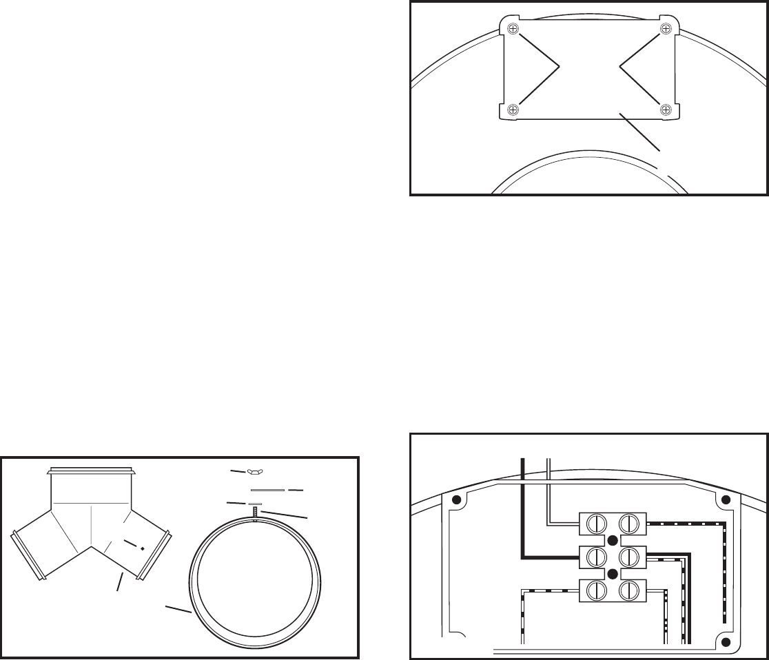
Supply from house
Blue
Black/Red
Brown
Red
Black
White
N
L
Figure 10
Figure 8
Damper
“Y” Transition
Hole
Wing Nut
Handle
Washer
Shaft