


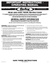
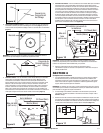
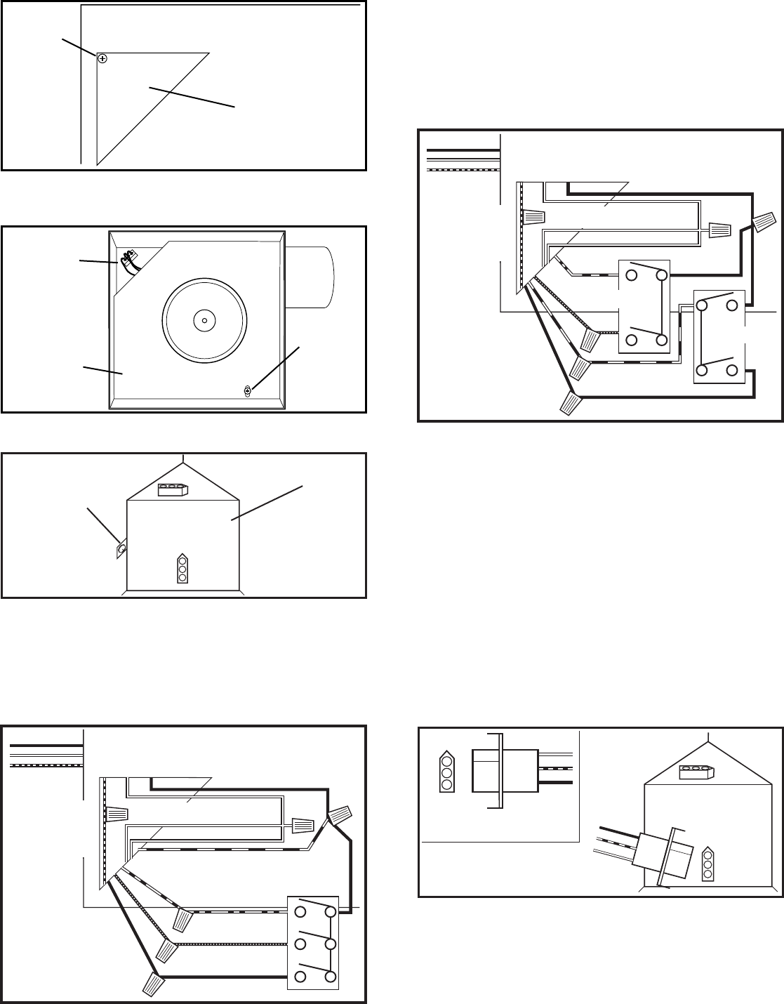
1b. Internal Wire Compartment: Remove the screw holding the blower assembly in place
and lift assembly out of housing (Figure 7). Remove the wire compartment cover screw
and place the cover in a secure place (Figure 8).
NOTE: If the fan motor plug is connected to the fan housing receptacle, unplug so the
blower assembly can be completely removed.
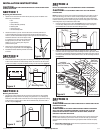
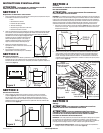
2. Continuous Ventilation: For two speed fans wired for continuous ventilation with the
recommended AKS3 switch (not included). Properly ground the switch. Connect the Black
(Hot) wire from the supply to both the Blue wire of the fan and a black wire run to the
common terminal of the wall switch. Run 3 wires from the wall switch (not included) to the
fan. Connect the Yellow wire from the fan to the top terminal of the AKS3 switch. This is
the light control. Connect the Purple wire from the fan to the middle terminal of the AKS3
switch. This is the night light control. Connect the black wire from the fan to the bottom
terminal of the AKS3 switch. This is the fan control and closing the switch will change
from normal to high speed (Figure 9).
www.airkinglimited.com
A210952014 Rev. G 6-15 3 of 12
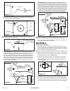
3. Intermittent Ventilation: For two speed fans wired for intermittent ventilation with the
recommended AKS4 switch (not included). Properly ground the switches. Run a wire from the
Blue wire in the fan to the Common terminal of one of the switches. Connect the Black wire
from the power source to the top terminal of the switch. This will turn the fan on and off. Run
a wire from the Black wire in the fan to the bottom terminal of the same switch. This is the fan
speed control and closing the switch will change from normal to high speed. On the second
switch run a Black (Hot) wire from the supply to the common terminal of the switch. On the
same switch run a wire from the Yellow wire in the fan to the top terminal of the switch. This
is the light control. Run a wire from the Purple wire in the fan to the bottom terminal of the
switch you just connected the yellow wire to. This is the night light control (Figure 10).
NOTE: The fan’s receptacle wires might need to be pulled outside compartment for connection.
Only pull the three loose wires outside of compartment. Additional wires will be present.
4. Carefully tuck wires back inside wire compartment and replace wire compartment cover
securing with the screw that was removed earlier.
SECTION 6
Completing the Installation
1. Use a sealant appropriate for contact with the building materials present and for the
temperature requirements of the installation to prevent air leakage from unconditioned
spaces is recommended. If gaps between unit housing and ceiling are great, additional
material (backing rod, ceiling material) may be required.
NOTE: This fan is rated for direct insulation contact (Type IC) and it is recommended that this fan
be completely covered by insulation in order to reduce heat loss or gain to unconditioned space.
2. If the fan’s blower assembly was removed during the wiring process, reinstall the blower
by reversing the directions in Step 1b in Section 5 Wiring.
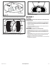
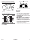
3. Plug the fan’s 5 pin quick connect motor cord into the receptacle on the side of the
wiring compartment cover and the light’s 4 pin quick connect into the receptacle on
the top of the wiring compartment cover. These cords will only fit one way into the
receptacles (Figure 11).
4. Install the included 26 watt fluorescent lamp into the lamp holder by lining up the pins on
the lamp base to the socket of the lamp holder and turning the lamp body clockwise until
the lamp snaps into place and is firmly seated in the lamp holder. Install a 4 watt maximum
type C7 (candelabra base) night light (not included) into the side lamp holder (Figure 12).
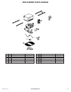
Figure 6
Screw
Wire
Compartment
Cover
Figure 8
Screw
Wire Compartment
Cover
Figure 11
Figure 9
Supply from
house
Hot (Black)
Blue
Black
Black
Switch
Neutral (White)
Ground
(Green or
Bare)
Yellow
Purple
Figure 10
Supply from
house
Hot (Black)
Black
Blue
Neutral (White)
Ground
(Green or
Bare)
Yellow
Purple
Black
Switch
Switch
Figure 7
Screw
Plug
Venturi