


6
Operating Manual -4048A digital signal processor
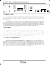
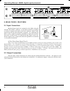
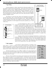
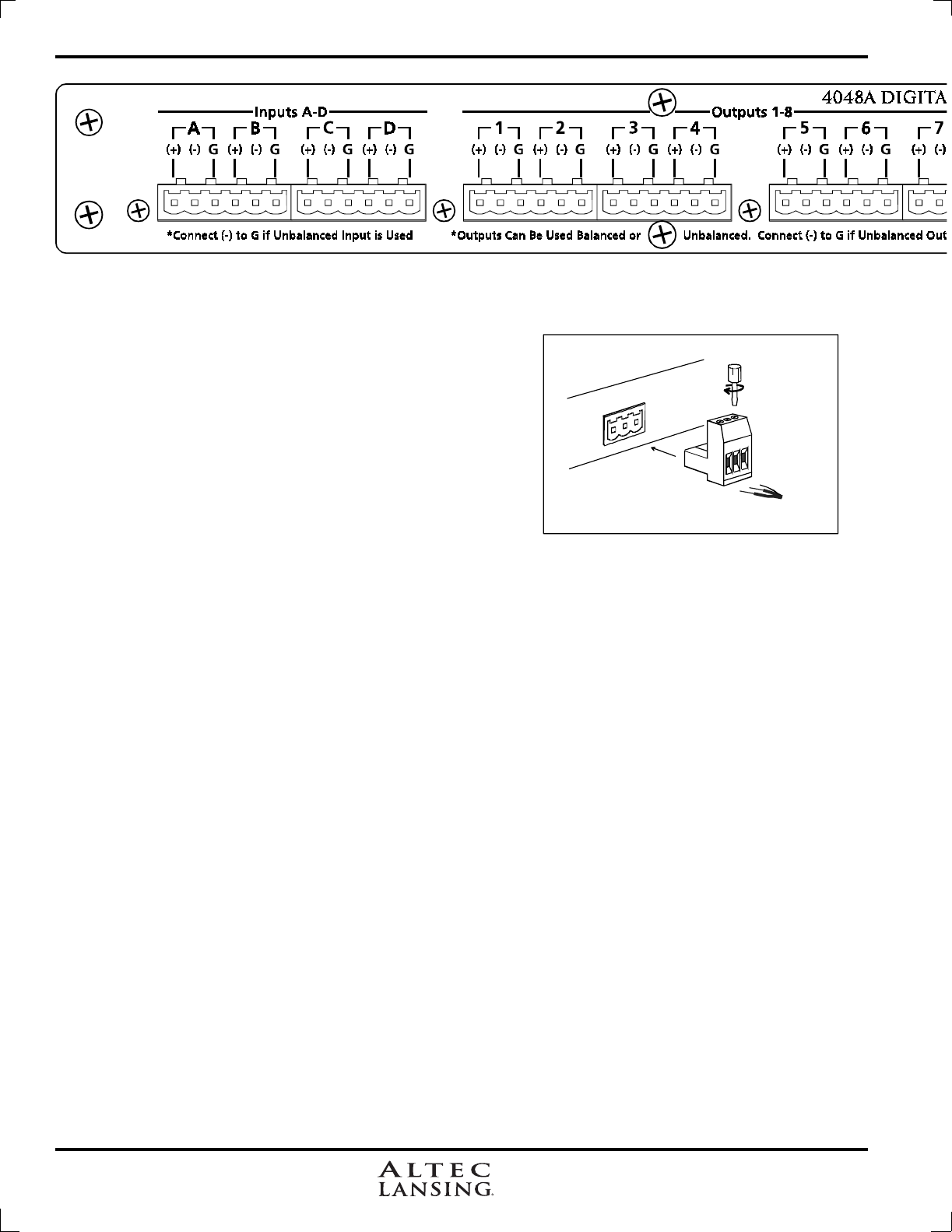
Euroblock
Connector
S
y
stem
+
-
G
+
-
G
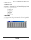
5. REAR PANEL FEATURES
5.1 Input Connections
Balanced input signals are connected to the 4048A using the
included "Euro Block" connector. A flat blade screwdriver is required
to connect a stripped wire lead to the loose connector, which is then
inserted into the rear panel Euroblock receptacle. It is important that
both (+) and (-) inputs are properly terminated or signal loss and noise
may result. In other words, if an unbalanced input signal is used, con-
nect the signal to the (+) input, and connect the ground wire to both the
(-) and ground connection.
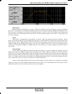
A Note About Input Signal Levels:
There are no input trim adjustments on the 4048A, therefore all the processing (including gain) is done in the
digital domain. As a consequence of this design philosophy, it is important to feed the processor with the proper
nominal signal level to achieve good signal to noise performance as well as headroom before clipping. The 4048A is
designed to clip at signal levels above +20dBu = 7.75Vrms which places the noise floor lower than -90dBu. The
optimum input signal level which should be fed into the processor is 0dBu = .775Vrms. This input level will allow
20dB of headroom while giving a nominal signal that is >90dB above the noise floor.
5.2 Output Connections
Like the inputs, output connections are made using the included Euroblock connector. All outputs are elec-
tronically balanced, and may be wired balanced or unbalanced. For unbalanced outputs, connect the shield to both (-
) and G terminals.