


5
Operating Manual-4048A digital signal processor
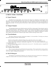
4. FRONT PANEL FEATURES
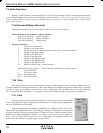
4.1 Input Channels
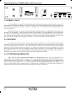
The 4048A has four input channels, each of which can be routed to any combination of output channels. Each
input channel's three color Sig LED indicates input signal level of -20dB (green), 0dB (amber), and +20dB clip (red)
respectively. Note that the Sig LEDs detect actual signal at the input connections, before any gain adjustments are
made within the 4048A. The red input mute LED becomes lit when an input channel is turned off through software
control.
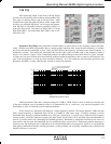
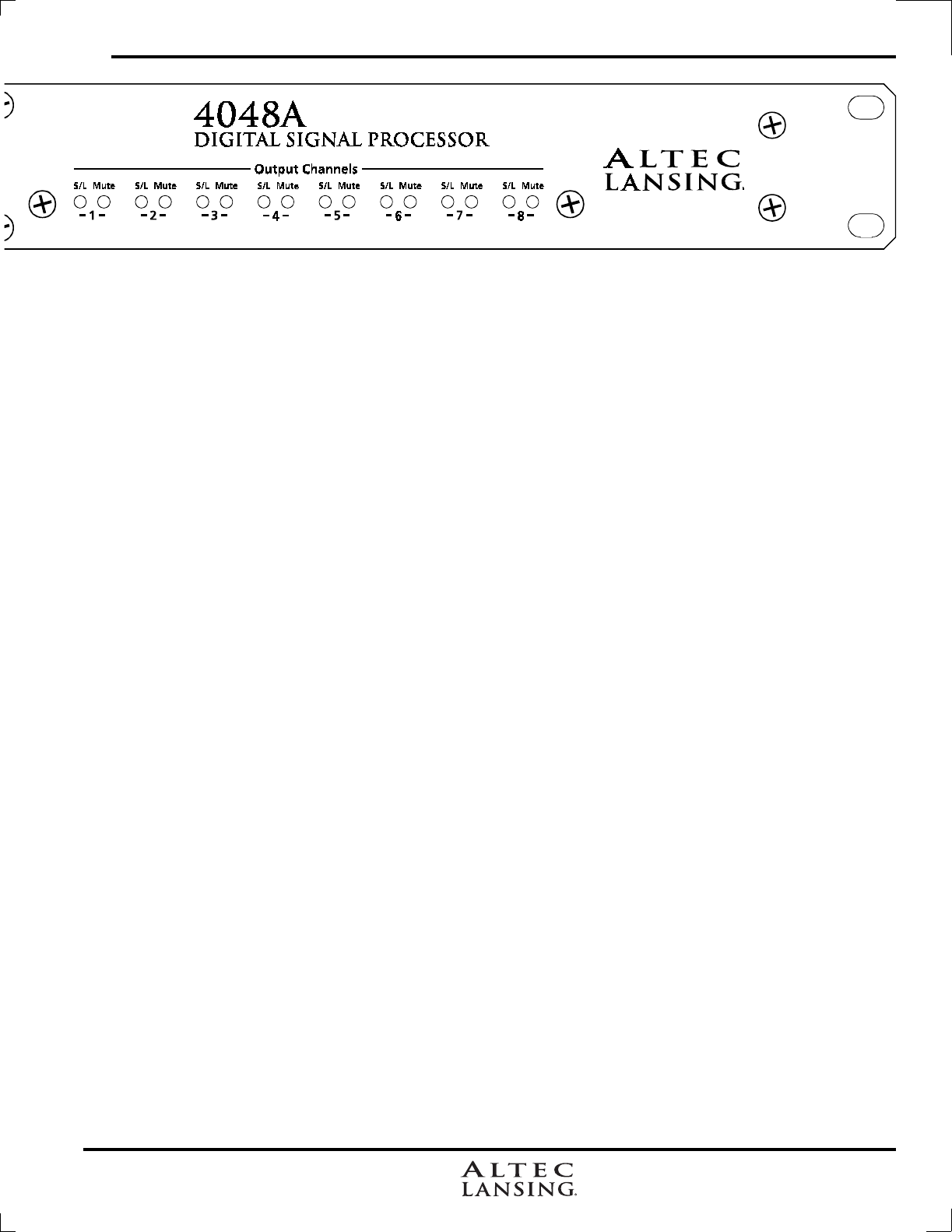
4.2 Output Channels
The eight output channels on the 4048A have three color LEDs to indicate signal, limiter threshold, and clip.
The green signal LED indicates -20dB output level. The amber limiter threshold LED depends on settings established
within Altec Lansing Software, and, assuming the limiter is active, indicates that sufficient signal level has been
reached for the limiter to begin the process of gain reduction. Clipping occurs at +20dB and is indicated by a red LED.
The red output mute LED becomes lit when an output channel is turned off through software control.
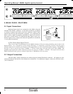
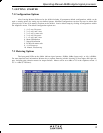
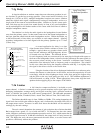
4.3 Preset Indicator
This display indicates the currently selected preset number (1-18) for the 4048A. This display also indicates
the following operating conditions within the 4048A:
- Firmware revision number is displayed during power up, and when a factory reset is aborted.
-
Factory reset countdown, which occurs by pressing and holding the factory reset switch during power up.
- Contact closure event confirmation is indicated by an upper case "C" for a few seconds, followed by the active
contact/preset number (1-8).
- RS-232 bulk preset dump completion is indicated by a lower case "d". If the 4048A receives a corrupt RS-232
dump, an upper case "E" is shown.
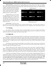
4.4 Factory Reset Switch
This is a recessed switch in the small hole below the preset display. This recessed switch is used to perform a
factory reset by pressing and holding during power up. Note that a factory reset will erase all user defined presets
stored in the 4048A, including the user password.
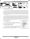
4.5 RS-232 Dataport
The 4048A has two parallel RS-232 dataports, one on the front panel and one on the back, for connecting to a
computer for software control. See section 6.3 for details on connecting to a computer.