


10
V. Gas Piping
IMPORTANT NOTE: This furnace is factory set to oper-
ate on natural gas at the altitudes shown on the rating
plate. If operation at higher altitudes and/or propane gas
operation is required, obtain and install the proper con-
version kit(s) before operating this furnace. Failure to
do so may result in unsatisfactory operation and/or equip-
ment damage. (High altitude kits are for U.S. installa-
tions only.)
The rating plate is stamped with the model number, type
of gas and gas input rating. Make sure the furnace is
equipped to operate on the type of gas available.
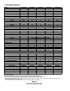
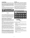
INLET GAS PRESSURE
Natural Min. 5.0" W.C., Max. 10.0" W.C.
Propane Min. 11.0" W.C., Max. 14.0" W.C.
Inlet Gas Pressure Must Not Exceed the Maximum Value Shown
in Table 3.
Table 3
The minimum supply pressure should not vary from that
shown in the table above because this could prevent
the furnace from having dependable ignition. In addi-
tion, gas input to the burners must not exceed the rated
input shown on the rating plate. Overfiring of the fur-
nace could result in premature heat exchanger failure.
High Altitude Derate (US. Installations Only -
Canadian Installations to 4500 Feet Only)
When this furnace is installed at altitudes above 2000
feet, the furnace input must be derated 4% for each 1000
feet above sea level because the density of the air is
reduced.
In some areas the gas supplier will derate the heating
value of the gas at a rate of 4% for each 1000 feet above
sea level. If this is not done, smaller orifices will be re-
quired at altitudes above 3500 feet (non-derated natu-
ral gas) or 4500 feet (non-derated propane gas).
A different pressure switch will be required at altitudes
more than 4000 feet above sea level. This is required
regardless of the heat content of the fuel used.
High altitude kits can be purchased depending on the
altitude and usage of propane or natural gas. Refer to
the high altitude instruction manual included with this
furnace to determine which high altitude components to
use.
Adjustment of the manifold pressure to a lower pres-
sure reading than what is specified on the furnace name-
plate is not a proper derate procedure. With a lower den-
sity of air and a lower manifold pressure at the burner
orifice, the orifice will not aspirate the proper amount of
air into the burner. This can cause incomplete combus-
tion of the gas, flashback, and possible yellow tipping.
Gas Piping
IMPORTANT NOTE: To avoid possible unsatisfactory
operation or equipment damage due to under firing of
equipment, do not undersize the natural gas/propane
piping from the meter/tank to the furnace. When sizing
a trunk line as shown in Table 4, include all appliances
on that line that could be operated simultaneously.
The rating plate is stamped with the model number, type
of gas and gas input rating. Make sure the furnace is
equipped to operate on the type of gas available.
The gas line installation must comply with local codes,
or in the absence of local codes, with the latest edition
of the National Fuel Gas Code (ANSI Z223.1).
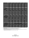
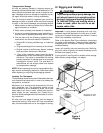
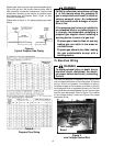
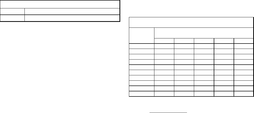
Connecting The Gas Piping - Natural Gas
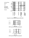
Natural Gas Capacity of Pipe
in Cubic Feet of Gas Per Hour (CFH)
Length of
Nominal Black Pipe Size (inches)
Pipe in Feet 1/2 3/4 1 1 1/4 1 1/2
10 132 278 520 1050 1600
20 92 190 350 730 1100
30 73 152 285 590 980
40 63 130 245 500 760
50 56 115 215 440 670
60 50 105 195 400 610
70 46 96 180 370 560
80 43 90 170 350 530
90 40 84 160 320 490
100 38 79 150 305 460
Pressure = .50 PSIG or less and Pressure Drop of 0.3" W.C. (Based
on 0.60 Specific Gravity Gas)
Btuh Furnace Input
Calorific Value of Gas
CFH=
Table 4
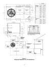
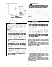
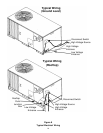
Refer to Figure 3 for the general layout at the furnace.
The following rules apply:
1. Use black iron or steel pipe and fittings for the build-
ing piping.
2. Use pipe joint compound on male threads only. Pipe
joint compound must be resistant to the action of
the fuel used.
3. Use ground joint unions.
4. Install a drip leg to trap dirt and moisture before it
can enter the gas valve. The drip leg must be a mini-
mum of three inches long.
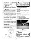
5. Use two pipe wrenches when making connection to
the gas valve to keep it from turning.
6. Install a manual shut-off valve in a convenient loca-
tion (within six feet of unit) between the meter and
the unit.
7. Tighten all joints securely.