


25
Flame Sensor (Qualified Servicer Only)
Under some conditions, the fuel or combustion air sup-
ply can create a nearly invisible coating on the flame
sensor. This coating acts as an insulator causing a drop
in the flame sensing signal. If this occurs, a qualified
servicer should carefully clean the flame sensor with
emery cloth or steel wool. After cleaning, the microamp
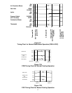
signal should be in the range listed in Table 1A.
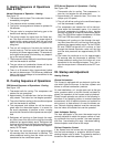
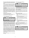
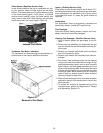
Figure 22
Induced Draft Motor
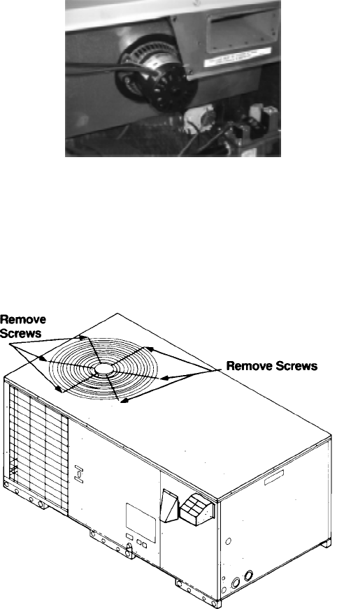
Condenser Fan Motor Lubrication
The condenser fan motor bearings are permanently lu-
bricated and do not require additional lubrication.
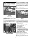
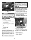
Figure 23
Removal of Fan Motor
Ignitor (Qualified Servicer Only)
If the ignitor and the surrounding air are at about 70° F
and the ignitor wires are not connected to any other elec-
trical components, the resistance of the ignitor should
not exceed 200 ohms. If it does, the ignitor should be
replaced.
Compressor
The compressor motor is permanently lubricated and
hermetically sealed. It does NOT require oiling.
Flue Passages
At the start of each heating season, inspect, and if nec-
essary clean the furnace flue passages.
Cleaning Flue Passages (Qualified Servicer Only)
1. Shut off electric power and gas supply to the fur-
nace.
2. Remove burner assembly and disconnect the gas
line and remove the manifold brackets from the par-
tition panel.
3. Remove the induced draft blower and the collector
box from the partition panel.
4. Remove tube inserts and turbulators from heat ex
changer.
5. The primary heat exchanger tubes can be cleaned
using a round wire brush attached to a length of high
grade stainless steel cable, such as drain cleanout
cable. Attach a variable speed reversible drill to the
other end of the spring cable. Slowly rotate the cable
with the drill and insert it into one of the primary heat
exchanger tubes. While reversing the drill, work the
cable in and out several times to obtain sufficient
cleaning. Repeat for each tube.
6. When all heat exchanger tubes have been cleaned,
replace the parts in the reverse order in which they
were removed.
7. To reduce the chances of repeated fouling of the
heat exchanger, perform the steps listed in Startup
and Adjustment, Section XII.