


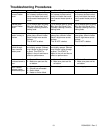
Troubleshooting Procedures
RS2420002 Rev. 515
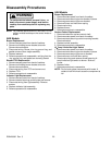
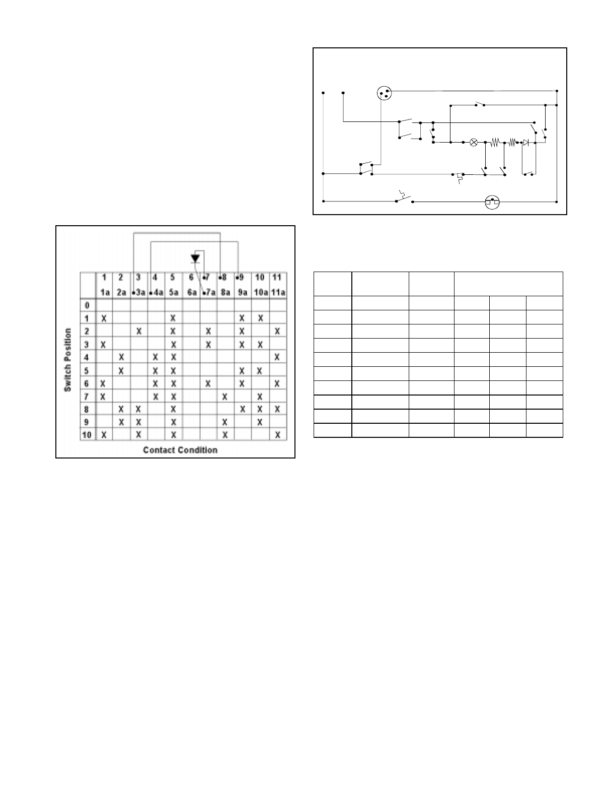
Multi
−
Position Switch
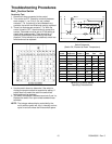
Continuity Test
1. Remove all wires connected to the control.
2. Turn control to OFF. Check for continuity between
each contact (1−1a, 2−2a, 3−3a, ect.) except
contacts 7−7a. If continuity is found between any
contacts, the switch has failed and must be replaced.
3. There is a diode across contacts 7−7a. With the
control turned to OFF, check continuity across this
contact. Ohmmeter must be set at 10 KΩ setting to
check diode measurement. There should be no
continuity one direction and continuity the other
direction. If this indication is not obtained, switch has
failed and must be replaced.
4. Use the matrix above to determine if the switch is
closing the proper contacts at a particular setting. If
switch does not match the matrix the switch has
failed and must be replaced.
5. The switch thermostat is between terminals 5 and 1a,
Replace the switch if an open exists between these
terminals.
NOTE:
The halogen element being controlled by the
multi−position switch will vary in intensity and not
cycle on and off unless the limiter switch opens.
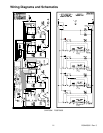
L1
N
"ON"LT
10a
11a
6a
5a
6
5
1b 2b
2a
1a
10 4a
4
3a
1
2
1a
2a
7
7a
9
8
9a
8a
L2
Lamp Inner Outer
4321
Switch Schematic
(Switch Off, Element at Room Temperature)
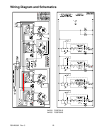
Switch
Power
Lamp
Brightness
Heater
Power %
Power Output (Watts)
1200 1500 1800
10 Full 100 1200 1500 1800
9 High 76 920 1145 1370
8 High 56 670 835 1000
7 Medium 41 495 620 740
6 Medium 30 360 450 540
5 Low 23 275 345 410
4 Low 16 190 240 290
3 Invisible 11 135 170 200
2 Invisible 8 100 125 150
1 Invisible 6 65 85 100
Haloring 10−Position Switch
Operating Characteristics