


Chapter 2 Interface Signals 5
25175H—March 2003 AMD Athlon™ XP Processor Model 8 Data Sheet
Preliminary Information
2 Interface Signals
This section describes the interface signals utilized by the
AMD Athlon™ XP processor model 8.
2.1 Overview
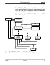
The AMD Athlon™ system bus architecture is designed to
deliver excellent data movement bandwidth for next-
generation x86 platforms as well as the high-performance
required by enterprise-class application software. The system
bus architecture consists of three high-speed channels (a
unidirectional processor request channel, a unidirectional
probe channel, and a 64-bit bidirectional data channel),
source-synchronous clocking, and a packet-based protocol. In
addition, the system bus supports several control, clock, and
legacy signals. The interface signals use an impedance
controlled push-pull, low-voltage, swing-signaling technology
contained within the Socket A socket.
For more information, see “AMD Athlon™ System Bus Signals”
on page 6, Chapter 11, “Pin Descriptions” on page 55, and the
AMD Athlon™ System Bus Specification, order# 21902.
2.2 Signaling Technology
The AMD Athlon system bus uses a low-voltage, swing-signaling
technology, that has been enhanced to provide larger noise
margins, reduced ringing, and variable voltage levels. The
signals are push-pull and impedance compensated. The signal
inputs use differential receivers that require a reference
voltage (V
REF
). The reference signal is used by the receivers to
determine if a signal is asserted or deasserted by the source.
Termination resistors are not needed because the driver is
impedance-matched to the motherboard and a high impedance
reflection is used at the receiver to bring the signal past the
input threshold.
For more information about pins and signals, see Chapter 11,
“Pin Descriptions” on page 55.