


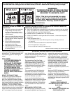
WARNING
TO REDUCE THE RISK OF
FIRE, ELECTRIC SHOCK,
OR INJURY TO PERSONS,
OBSERVE THE
FOLLOWING:
A. Installation Work and Electrical
Wiring Must Be Done By Qualifi ed
Person(s) In Accordance With All
Applicable Codes And Standards,
Including Fire-Rated Construction.
B. Suffi cient air is needed for proper
combustion and exhausting of
gases through the fl ue (chimney) of
fuel burning equipment to prevent
back drafting. Follow the heating
equipment manufacturer’s guideline
and safety standards such as those
published by the National Fire
Protection Association (NFPA), and
the American Society for Heating,
Refrigeration and Air Conditioning
Engineers (ASHRAE), and the local
code authorities.
C. When cutting or drilling into wall or
ceiling, do not damage electrical
wiring and other hidden utilities.
D. When used as exhaust fans,
ducted fans must always be vented
to the outdoors.
E. If this unit is to be installed over a
tub or shower, it must be marked as
appropriate for the application and be
connected to a GFCI (Ground Fault
Circuit Interrupter) - protected branch
circuit.
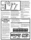
White
Brown
Factory Wiring for
IP Protected Motors
White
Black
Neutral
Ground
115 V
Black
White
Brown
Black
Factory Wiring
Field Wiring
Field Wiring
Green/Yellow
Green/Yellow
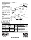
anchors are recommended. The rubber
grommets provide vibration isolation.
The brackets should be attached to the
fan fi rst. Then install the wood screws at
the keyhole locations and install the fan.
The fan may also be mounted on a foam
rubber pad on a fl at surface, such as an
attic fl oor.
COLD CLIMATE PRECAUTIONS
If installed in an unheated space, in
cold climates, there is a possibility
of condensation forming in the fan
housing or ducting components. A
backdraft damper installed at each
grille is very effective in reducing the
potential for condensation when the fan
is cycled on and off. Insulated ducting
must be used where exposed to cold
attic or crawl space temperatures, to
avoid condensation in the ducting.
Condensation can also be avoided by
continuous operation of the fan.
DUCT CONNECTIONS
Ducting may be fl exible or rigid,
depending on local codes. If permitted
by code, insulated fl exible ducting is
recommended for at least several feet on
each duct connection, to limit fan noise at
the outlet grilles. Ducting should conform
to NFPA 90A and meet the requirements
of Underwriters Laboratory as a Class O
or Class 1 duct to specifi cation UL 181,
Standard for Factory-Made Air Ducts and
Duct Connectors. Metal ducting must
be sealed on both the end joints and
longitudinal seams to avoid duct leakage
and assure proper airfl ows at the grilles.
MAINTENANCE
Monthly:
Inspect and clean the exhaust grilles and
fi lters, if so equipped.
Annually:
To ensure the maximum effi ciency of
the fan unit, is recommended to clean
the inside of the fan box as well as the
blower wheel.
CAUTION:
Automatically operated device—to
reduce risk of injury disconnect from the
power supply before servicing.
DISASSEMBLY
Turn off all power to the unit. The blower
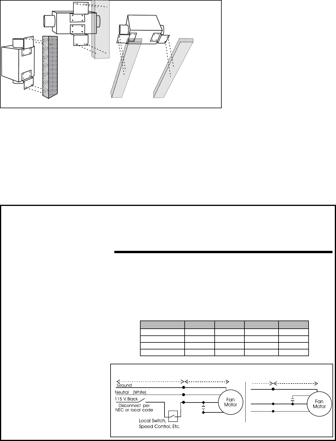
ELECTRICAL
FANS MAY BE MOUNTED VERTICALLY OR HORIZONTALLY
Provide disconnect switch in vicinity of fan, to
permit servicing fan, in accordance with NEC
and local codes.
Depending on the desired mode of operation,
switches may be simple on-off switches,
motor speed controls, timer switches, time
delay, time of day cycle timers, dehumidistats,
F. NEVER place a switch where it can
be reached from a tub or shower.
occupancy sensing controls, controllers,
etc., provided they are rated for motor duty
and meet the nameplate electrical ratings
of the motor. (Additional application wiring
diagrams are available illustrating a variety
of controls for use with RDF fans by calling
the factory at 1-800-255-7749.)
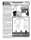
ELECTRICAL DATA
Base Model Volts Max Amps Max Watts RPM
RDF 8-8IP 115 0.19 21 2500
RDF 8-8MAX 115 0.29 34 3135
RDF 12-8IP 115 0.34 41 2200
RDF 12-8 115 0.53 59 2960
RDF 8MAX
and RDF 12-8
RDF 8-8 IP and
RDF 12-8 IP