BRADENTON, FL 34203
P: 941.351.3441
F: 941.351.3442
E: info@aldes-us.com
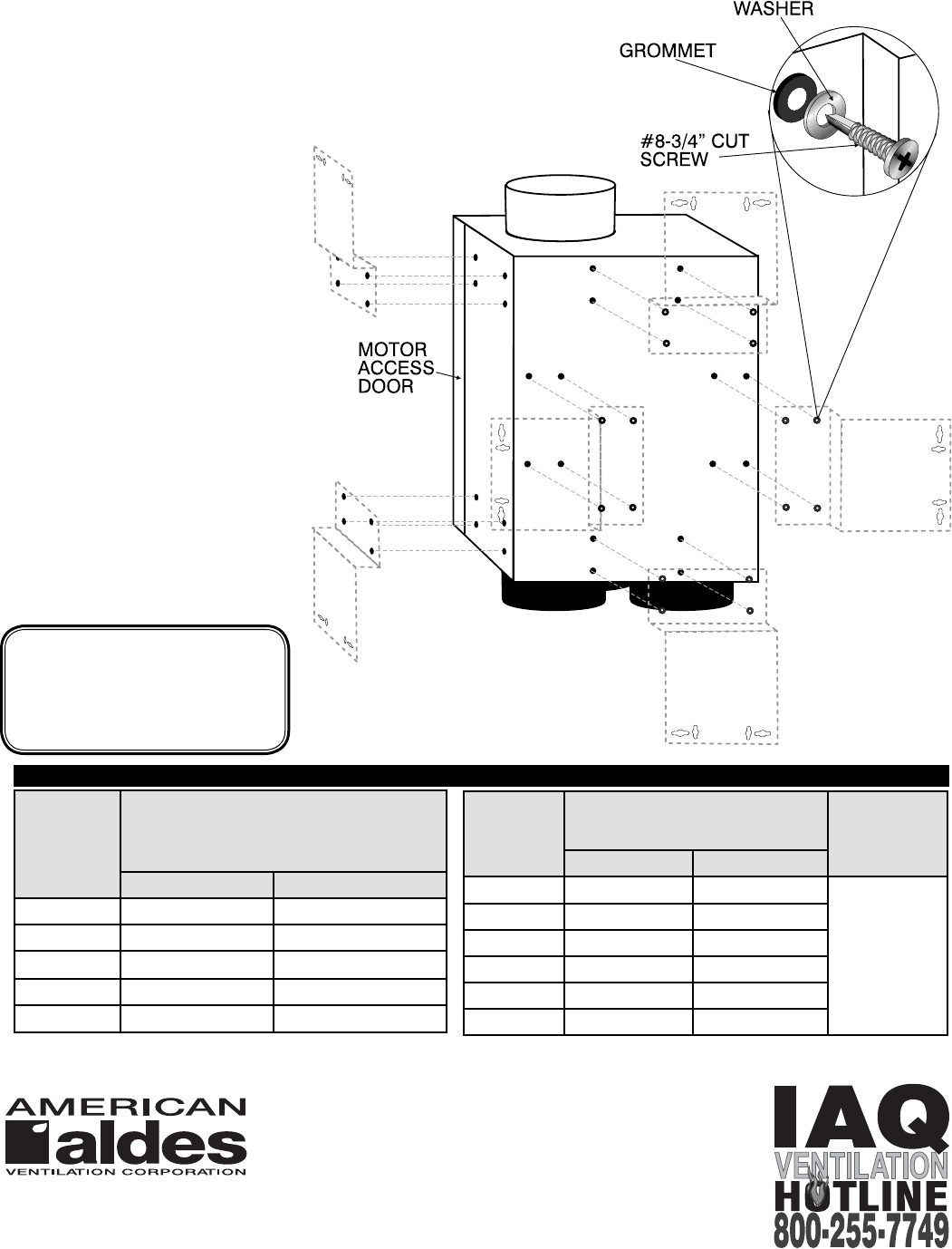
operation. The entire motor and fan
assembly is mounted on a drop-down
hinged access panel for service and
inspection, and can be removed from
the fan without disassembly of the
ducting connections.
Controls: The fans can be operated
manually, or automatically by a
programmable timer or dehumidistat
and may also be operated in
conjunction with a variable speed
control.
Locating and Installing the Fan:
The compact dimensions and
versatile mounting options permit
installation above drop ceilings,
between ceiling joists, or within a
small soffi t location. The fan can
be installed either horizontally or
vertically.
Airflow Balancing: The flow
rates are automatically set with
preset ALDES Constant Airflow
Regulators.
A passively controlled element in
each duct run infl ates or defl ates
automatically in response to system
pressure to maintain constant
airfl ow.
02/09
www.americanaldes.com
AIRFLOW
CFM
3" INTAKE DUCT TO FAN
Recommended
Max. Duct Length from
Grille to Fan (ft.)
SMOOTH FLEXIBLE
10 225 180
20 65 50
30 30 25
40** 20 15
50** 10 10
*This table should only be used as a general guide. Actual duct length allowances may be longer on some models. Contact the factory for
assistance. **CAR Flow Regulators not available over 35 cfm. NOTE: If longer duct runs are required than permitted in the table above, use smooth
ducting and/or increase the diameter.
ELECTRICAL DATA
MPVS 100 / 120
120 V, 60 Hz., .19/.29 amp.,
22/38 W Max., 2980 / 3135 RPM
Above ratings are intended for sizing
electrical wring only. Actual consumption
will be lower.
TOTAL
EXHAUST
RATE CFM
FAN DISCHARGE DUCT
Assumes low pressure drop
vent cap
FOR EACH
ELBOW
DEDUCT
4" SMOOTH 4" FLEXIBLE
60 40 ft 20 ft
3" Diameter
= 3 Feet
75 25 ft 15 ft
90 18 ft 12 ft
100 15 ft 9 ft
120 11 ft 8 ft
135 8 ft 6 ft
MOUNTING BRACKET
LOCATIONS
TABLE OF AIRFLOWS AND DUCT LENGHTS*


