


4
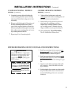
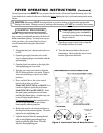
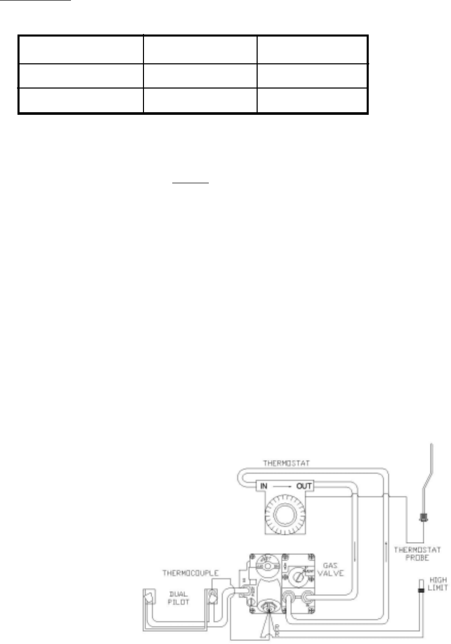
Figure 1. Fryer Model 14GS Wiring Diagram
Figure 1 is a wiring diagram of an
ANETS 14GS Fryer. Some fryers
may have other options that do not
appear in this basic wiring diagram. A
model-specific wiring diagram included
with each fryer shows all the actual parts
and their associated wiring connections.
In addition, a fryer equipped with a built-
in filter sys- tem (Filtronic II or Filter
Mate) has a supplementary manual
included for that option.
FRYER ELECTRICAL SPECIFICATIONS
The ANETS Fryer Models 14GS, 14GSU, MX-14EG, and MX-14EGU require no exter-
nal electric power source.
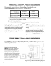
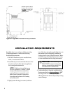
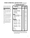
FRYER GAS SUPPLY SPECIFICATIONS
Please make sure that your desired fryer location has gas
supply factors that are suitable for this product:
Natural Gas Propane
3½“ W.C.
**
10“ W.C.
6“ W.C., minimum 11“ W.C., minimum
INPUT REQUIRED:
SUPPLY PRESSURE***
MANIFOLD PRESSURE
111,000 BTU
*
BTU/Hr Rating is based on sea level operation. For sites above 2000 feet, reduce this
rating 4% for each 1000 feet above sea level.
“ W.C. = Inches, Water Column.
Measure Supply Pressure when all other gas-powered equipment is operating.
* -
*** -
** -
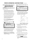
Gas Supply Inlet Pipe size must be ¾“ NPT
(National Pipe Thread) standard gas line. The gas
supply inlet line should be as straight as possible
(fewest bends or elbows) to obtain the highest
available gas pressure at the fryer. Locate this
inlet line horizontally at the center of the desired
fryer location, 8¼“ above the floor.
NOTE: Using a flexible inlet line permits variation
in the gas supply line location, both horizontally and
vertically.
Anets fryers are only for use with the type of gas
specified on the spec plate. if a fryer requires
modification to use a gas other than that which is
identified on the fryer spec plate, contact you Anets
representative or call (800) 837-2638.