


13
P/N 1010807 Rev. E 06/06
VERTICAL CONTACT TOASTER
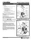
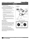
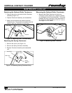
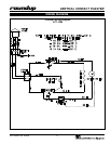
Figure 11. Removing Conveyor Belt Chain
Rotation
Upper Support Rod
Large Link
P/N 0800121
Small Link
P/N 0800204
Conveyor Belt Chains
MEASURING CONVEYOR BELT CHAINS
Facing the toaster, locate the approximate center-point
of the Conveyor Chain. Pull the Conveyor chain away
from the edge of the toaster. Stand a U.S. Dime, 11/
16” (1.8 cm) coin on end between the frame and the
chain. If the gap is significantly wider than the coin,
REMOVE links as described below. Then, measure
the gap again to make sure it is not too tight. Check
the opposite side of the toaster using the same mea
-
surements.
ADJUSTING CONVEYOR BELT CHAINS
After a period of time, the Conveyor Chain links will
wear and the Conveyor Belt chain will stretch, eventu
-
ally skipping on the lower sprockets. This is easily
remedied by removing one or more conveyor links from
each side of the belt. There are two 1/2” small links
on
each side of the conveyor belt. The rest of the links
are large, 3/4” long (Figure 11).
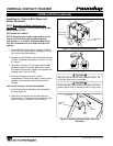
REMOVE CONVEYOR BELT CHAINS
1. If required, perform steps 1 - 4 under
Replacing
Belt Wraps
on the previous page.
2. Disconnect the Conveyor Belt Chain by squeez
-
ing any two links together and unhooking both
ends of one link (Figure 11). Needle-nose pliers
may be used.
3. To shorten a stretched Conveyor Belt Chain,
remove one 1/2” link from the belt.
4. Reassemble the Conveyor Belt Chain onto
the sprockets as described below in Replacing
Conveyor Belt Chains.
NOTE: If the belt is too short to be reassembled,
remove an additional 1/2” small link and install a
3/4” large link. This will shorten the belt 1/4” over
-
all.
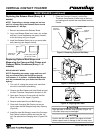
REPLACING CONVEYOR BELT CHAINS
1. Remove the old Conveyor Belt Chain as
described above.
2. Place the replacement Conveyor Belt Chain on
the top sprockets with hook ends down. Check
for correct positioning (Figure 11).
NOTE: The ends of the hooks must point down.
(Figure 11).
3. Wrap the Conveyor Belt Chain around the top
and lower sprockets and connect by hooking both
ends together.
NOTE: Make sure the Conveyor Belt Chain is
installed under the upper support rod and over the
lower support rod.
WARNING
Turn the unit off, disconnect the power source and
allow the unit to cool down before performing any ser
-
vice or maintenance on the unit.
NOTE: The Bun Thickness Compression Knobs
(Figure 7) must be set to “6 & 6” prior to measur
-
ing or removing or reinstalling the Conveyor Belt
Chains.