


INSTALLATION
1. Examine carton for damage
The freight carrier has assumed responsibility for its safe transit and delivery. If equipment is
received damaged, either apparent or concealed, a claim must be made with delivering carrier.
a. Apparent damage or loss must be noted on the freight bill at the time of delivery.
The carrier representative (Driver) must sign the freight bill. If this is not done, the
carrier may refuse the claim. The carrier can supply the necessary forms.
b. Concealed damage or loss if not apparent until after the toaster is removed from
carton, a request for inspection must be made to the carrier within 15 days. The carrier
should arrange an inspection. Be sure to save all contents and packaging material.
2. Verify Parts
After removing unit from the shipping carton, unwrapping loose parts and remove any packing tape,
plastic wrap and nylon tie-down. Verify the following parts:
Item Packaging Qty
Legs In plastic bag 4
Feeder/Bun Chute Wrapped, loose in top of carton 1
Conveyor In individual carton 1
Instruction Manual Loose in carton 1
Teflon Sheet Kit (optional) Loose in carton Optional
NOTE: PRIOR TO INITIAL START-UP, ALL REMOVABLE PARTS AND THE GRILL SURFACE SHOULD
BE CLEANED WITH WARM SOAPY WATER TO REMOVE MANUFACTURING OILS, THEN RINSED
AND DRIED THOROUGHLY. Apply oil (vegetable oil) to the conveyor chain after washing. (Bun oil can be
used if it contains no animal fats, salts or dairy products).
3. Assemble Legs
Lay the toaster on its back and install the four adjustable legs into the threaded holes on the bottom
of the toaster sides. Hand tighten the legs by gripping the black shank and turning until it is seated
firmly against the bottom of the toaster. Set the toaster upright on a flat surface. Unscrewing the
lower, chrome insert of each leg levels the unit. Flats are provided on two sides of the insert to allow
use of a wrench. “Precise” leveling is not required for proper operation.
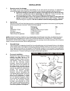
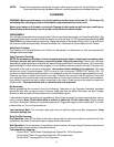
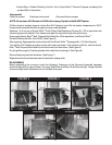
4. Conveyor Installation
Remove the front panel by lifting it
straight up. (See Figure 1) Lift
conveyor assembly by using “U”
shaped handles on each conveyor
side bracket. Lower the conveyor
into the two conveyor hanger
brackets above the grill plate on
each side, so the four spacers on
the sides of the conveyor rest on
the bottom flange and the bottom
spacers are against the adjustment
screws. The conveyor hanger
brackets are factory adjusted.
However, before reinstalling the
front panels apply power to the unit
and run the conveyor to insure
proper gear engagement. If gears
are not properly engaged, adjust
the conveyor by loosening the jam
nuts on the conveyor hanger
brackets and adjusting the screw
(see Figure 2) to set the conveyor to
the correct height. Retighten lock
nuts after adjustment is complete.
3
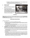
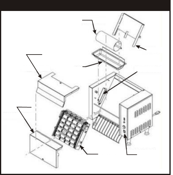
FIGURE 1. M2000 ASSEMBLY DRAWING
Bottom
Front
Panel
Top Front Panel
Feeder
Conveyor
Hanger
Main Power
Switch
Conveyor
Assembly
Butter Roller
Butter Pan