


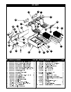

2. DESCRIPTION
Electric Fryers:
These electric units are designed for countertop operation. They are used for producing evenly cooked,
perfectly fried products.
5
3. INSTALLATION
1. Follow General Installation Instructions on previous page.
Screw legs into the permanently fastened nuts on the four corners of the unit and tighten by
hand. Level the fryer by turning the adjustment screw at the bottom of each leg. Do not slide unit with
legs mounted, lift if necessary to move unit.
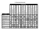
These values are nominal ratings. Field wire connections must be capable of withstanding
anticipated surges.
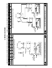
For testing, see the wiring diagrams in this manual for the rated amperages.
NOTE:
!
!
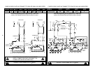
4. THERMOSTAT CALIBRATION
Checking Thermostat Calibration:
MAX MIN
The fryer thermostat is carefully calibrated at the factory so that dial settings match actual frying compound
temperatures. Field re-calibration is seldom necessary unless the unit has been mishandled in transit or
abused. Re-calibration should not be resorted to unless considerable experience with cooking results
definitely proves that the control is not maintaining the temperature to which the dial is set.
1. To check compound frying temperatures when re-calibrating, use a precision test instrument, or a
good grade mercury thermometer. Fill the tank half way between the and marks on the
tank.
2. Frying compound temperature should be checked at the center of the tank, approximately 1” to
11/2” belowsurface offryingcompound.
3. Turnthe dialof thethermostatbeingchecked tothe 350°Fmark.
4. Allow temperature to stabilize, or until the thermostat cycles to “OFF” three times after starting
with cold frying compound. With power “ON”, read highest and lowest frying compound
temperature,as thermostat cyclesthroughat leasttwo cycles.Averagethereading.
5. Thermostat should be re-calibrated if temperature reading is not within 10 degrees of the
control knob setting (350°F +/- 15°F). If re-calibration is required, continue with steps 6, 7, 8 and 9.
6. Remove control knob by grasping outer edge and pulling straight out, without twisting or turning.
7. Hold thermostat dial shaft “B” (Figure 1) stationary with pliers, and with a screwdriver, turn screw “A”
clockwise to obtain a lower temperature; or counter-clockwise for higher temperature. Each ¼ turn
(90° rotation) of screw “A” represents 18°F.
8. Replace thermostat control knob.
9. Recheck thermostat as in Steps 4 and 5 above. If the fat temperature is not within 20 degrees of dial
setting (350°F +/- 20°F), it means that the sensing element is inoperative and the thermostatic
control should be replaced.