


4
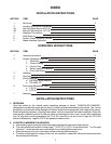
2. CO11-2E: INSTALLATION / MOUNTING 6” LEGS
a. After unpacking the unit, remove legs and any other material from inside the oven.
b. Tilt the bottom oven onto its left side and attach the two mounting plates to the right underside using
½” bolts and washers and tighten firmly. Screw the 6” legs into the center holes.
c. Use proper lifting equipment to raise the unit, and while suspended attach the two left mounting
plates and legs in the same manner.
d. Use the lifting equipment to raise the top oven to the proper height, and slide it on top of the bottom
oven. Line up the sides and front and use the supplied stacking brackets, screws and lock washers
to fasten the two ovens in the back.
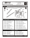
3. CO11-E1: ASSEMBLY OF AN OPEN RACK STAND (see Sketch “D”)
a. Slightly loosen the (12) 30” leg bolts.
b. Remove (4) inner bolts, (1) from each of the four legs, place the top right angle underneath as
shown, and tighten these (4) bolts.
c. Insert Open Rack Shelf and tighten into place with (8) 3/8”-16 screws, washers and nuts.
d. Position Rack Supports and tighten in place using (4) 5/16”-18 hex nuts and flat washers.
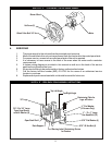
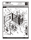
4. COC-E / CO11-E1: INSTALLATION OF CASTERS (Optional)
a. (4) Casters (2) with wheel brakes and the mounting hardware is packed and included in the
shipment if ordered.
b. Install casters with wheel brakes on the front of the unit. Note: One leg has a warning label affixed.
This leg must be positioned so the label faces the front of unit (see page 9, sketch D).
c. Install rear legs with casters on the back of the unit with the restraining plate affixed firmly between
the right rear leg & the bottom of the appliance as shown on page 9.
d. Provide a suitable restraining chain or cable to securely tether the appliance to the building
structure. The restraining chain or cable should be of such length, that it will stop movement of the
appliance before there is any strain on the power supply cable.
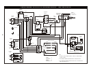
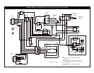
4. ELECTRICAL CONNECTIONS
1. GENERAL INSTRUCTIONS
a. A licensed electrician must make electrical connections.
b. When installed, unit must be electrically grounded in accordance with the local codes and/or the
latest edition of the National Electrical Code ANSI/NFPA No. 70 in USA or Canadian Electrical
Code, CSA Standard C22.1, Part 1 in Canada.
c. Make sure electrical supply corresponds with that specified on the rating plate.
d. For single phase 2-wire or three phase 3-wire supplies, the controlling branch circuit is designed to
operate at 208-240 volts AC and is pre-wired at the factory between L1 and L2 of the field wiring
terminal block (in North America).
e. For three phase 4-wire 230/400 Volts AC 50hz supplies, the controlling branch circuit is designed to
operate at 230 volts AC and is pre-wired at the factory between L2 and N of the field wiring terminal
block.
f. Only use copper conductors rated at 90°C.
g. All pole disconnect must be provided by the installer.
h. FOR CE UNITS: The appliance must be connected by an earthing cable to all other units in the
complete installation and thence to an independent earth connection in compliance with EN 60335-
1 and/or local codes. If flexible line cordage is used to connect the equipment, it should be a
minimum of H07RN-F type conforming to EN60335-1, EN60335-2-42 and/or local codes.
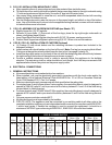
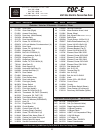
Amps Motor - 50hz Motor - 60 hz
Model kw Voltage Phase Line 1 Line 2 Line 3 N RPM - Lo RPM - Hi RPM - Lo RPM - Hi
COC-E: POWER SUPPLY
COC-E1 9.5 208 3 27.1 27.1 25.0 - - - 1140 1725
8.7-10.3 220-240 3 23.4-25.5 23.4-25.5 21.6-23.6 - - - 1140 1725
9.5 208 1 45.7 45.7 - - - - 1140 1725
8.7-10.3 220-240 1 39.5-43.1 39.5-43.1 - - - - 1140 1725
9.5 230-400Y 3 13 13 15.2 2.2 950 1425 - -
9.5 230 1 41.3 - - 41.3 950 1425 - -
Each oven requires separate electrical connections