


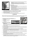

Figure 31
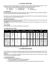
Figure 32
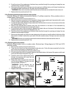
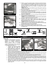
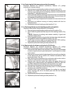
7. Pull the copper thermostat probe and tubing from the fan blower
motor assembly area through the opening to the front cover (it
may be necessary to feed the probe, into the bottom of the
assembly area under the fan blower to achieve the correct
angle). (Fig. 31)
DO NOT bend or kink the copper tubing when replacing
the thermostat probe.
8. Disconnect wires from rear of thermostat by reversing screw
terminals with a flathead screwdriver.
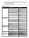
9. Connect wires to the rear of a new thermostat unit using the
thermostat wiring diagram for CA70 units. Re-tape over wire nuts
and wires. (Diagram 4)
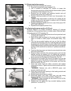
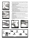
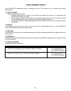
10. Attach new thermostat to rear of front panel and bezel to the front
of panel with the two phillips screws.
The tops of the terminals should face down (toward the
actual top of the heating module). (Fig. 32)
11. Carefully guide new copper probe and tubing through the
opening to fan blower motor housing and reattach probe clips
with two flathead screws. (Fig. 31)
DO NOT kink or bend the copper probe or tubing.
12. Replace fan blower motor assembly cover with two front and two
rear flathead screws. Do not over tighten.
13. Replace thermostat dial, tightening set screw securely.
14. Replace top mounted heating module and front panel (sections
6-1a and 6-1 b).
**NOTE:
**NOTE:
**NOTE:
Diagram 4
6-1j Replacing the thermostat for
CA43 units.
Required: Small flathead screwdriver,
Medium (6”) flathead screwdriver,
Medium (6”) phillips screwdriver,
Wiring markers (color or number
codes), Electrical tape, Wiring diagram
for thermostat (see step 11)
1. Remove top mounted heating
module and front panel as
found in sections 6-1a and 6-1b.
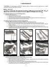
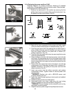
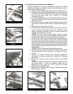
2. Mark all the wires connected to
the power cord with a color
code or number to make proper re-connection easy. (Fig. 33)
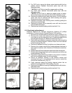
3. Remove thermostat dial from front panel by rotating the dial to expose the set screw and reversing
the sat screw with a small flathead screwdriver. (Fig. 34)
4. Remove the two screws holding the bezel (chrome ring) behind the thermostat dial with a medium
(6”) phillips screwdriver. Carefully pull thermostat away from the rear of the front cover.
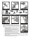
5. Remove the fan blower motor assembly cover (on the left side of module as you are facing the front
panel) by removing the two front and two rear screws with a medium (6”) flathead screwdriver. (Fig. 35)
6. Pry off fan blower housing cover (with a flathead screwdriver, if necessary). Without disconnecting
wires, set cover on a clean work area. (Fig. 36)
7. Remove four screws (two at each end) holding fan blower motor bracket in place with a medium
flathead screwdriver and gently lift bracket to expose mounting clips for the copper thermostat
probe. (Fig. 37)
Figure 33
Figure 34