


Manual 2100-498B
Page 7 of 17
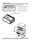
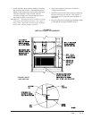
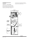
9. Mount mixed air thermistor sensor to blower as
shown with screws provided. Route two (2) red
wires from wire harness installed in Step #7 through
cable holders, and connect to thermistor sensor as
shown in Figure 2.
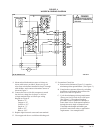
10. Connect the wires (with fork connectors) routed
into the low voltage box in Step #7 to the low
voltage terminal strips as follows per wiring
diagram on Figure 4:
Black to “C”
Orange to “G”
Yellow to “Y1”
Purple to “Y”
Pink to “Y2”
Blue to “W1”
11. Replace right front unit corner and vent terminal.
12. Close upper unit door to seal blower discharge air.
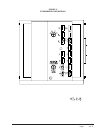
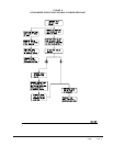
FIGURE 4
WGSEIFM-5 WIRING DIAGRAM
BLBLUE
PINK PK
PURPLE
PR
Y
YELLOW
Y
ORANGE
ORANGE
O
O
ORANGEBROWN
R
RED
R
RED
RED
LOGIC MODULE
UNIT
24 VOLT
TERMINAL
STRIP
EIFM
CONTROL PANEL
UNIT BLOWER SECTION
11
22
3
3
66
55
4
4
8
8
7
7
PL1
PL2
BLACK
SERVICING
!
S
+
C
G
Y
Y1
R
Y2
F
E
W1
W2
1
2
3
13
4
7
A
B
6
9
TH
P
P1
T1T
4
3
1
2
5
+
Sr
So
BK
6
ENTHALPY SENSOR
TR
16
TR1
BLACK
4
DANGER
+
* DISCONNECT POWER BEFORE
5
RELAY
CONROL
* ELECTRICAL SHOCK HAZARD
7
7
7
8
9
7
7
7
7
7
7
7
6
7
A
4056-197 B
13. Economizer Check Out
A.
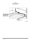
Remove mist eliminator (Figure 2). Locate the
minimum position potentiometer. (See Figure 5.)
B. Energize the evaporator blower by switching
thermostat to the manual fan position with
heat/cool in the OFF position.
C. Cycle the minimum position potentiometer
(factory set for 0% fresh air) 0 to full open.
(See Figure 5.) Throughout checkout
procedure observe operation of damper to
insure there is free, unobstructed operation
through the entire angle of damper travel.
Then adjust the damper minimum open
position to meet local codes or application
requirements. See example below.