


- 6 -
the cooking pots on the cooker top and the lowest part of
the cooker hood must be at least 65 cm. If a connection tube
composed of two parts is used, the upper part must be placed
outside the lower part. Do not connect the cooker hood
exhaust to the same conductor used to circulate hot air or for
evacuating fumes from other appliances generated by other
than an electrical source. Before proceeding with the assembly
operations, remove the anti-grease lter(s) (Fig.7) so that the
unit is easier to handle.In the case of assembly of the appliance
in the suction version prepare the hole for evacuation of the air.
•We recommend the use of an air exhaust pipe with a di-
ameter of 150. If a pipe with a smaller diameter is used, the
eciency of the product may be reduced and its operation
may become noisier.
Please note:
If your version of the appliance has decorative glass before
installing the hood, carry out the following steps as shown
in gure 4:
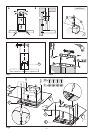
1 - Remove both the cooker hood body B and the glass
panel A from the packaging and place them horizontally on
a secure surface.
2 - Take the glass panel A and position it above the cooker
hood body B.
3 - Fix the glass panel securely to the cooker hood body using
the 4 sleeves C and 4 screws D as indicated.
•Fixingtothewall
Drill the holes A respecting the distances indicated (Fig.2).
Fix the appliance to the wall and align it in horizontal posi-
tion to the wall units. When the appliance has been adjusted,
denitely x the hood using the screws A (Fig.5). For the
various installations use screws and screw anchors suited to
the type of wall (e.g. reinforced concrete, plasterboard, etc.). If
the screws and screw anchors are provided with the product,
check that they are suitable for the type of wall on which the
hood is to be xed.
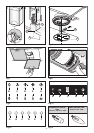
•Fixingthedecorativetelescopicue
Warning! Caution! If your appliance model features the lower
connector with a tab, before xing it in place bend the tab
inwards using a pair of pliers, as illustrated in gure 5, step1.
Arrange the electrical power supply within the dimensions of
the decorative ue. If your appliance is to be installed in the
ducting version or in the version with external motor, prepare
the air exhaust opening. Adjust the width of the support
bracket of the upper ue (Fig.3). Then x it to the ceiling using
the screws A (Fig.3) in such a way that it is in line with your hood
and respecting the distance from the ceiling indicated in Fig.2.
Connect the ange C to the air exhaust hole using a connection
pipe (Fig.5 - Stage 2). Insert the upper ue into the lower ue.
Fix the lower ue to the hood using the screws B provided
(Fig.5 - Stage 2), extract the upper ue up to the bracket and
x it with the screws B (Fig.3). To transform the hood from a
ducting version into a ltering version, ask your dealer for the
charcoal lters and follow the installation instructions.
•Filteringversion
Install the hood and the two ues as described in the para-
graph for installation of the hood in ducting version. To as-
semble the ltering ue refer to the instructions contained
in the kit.
If the kit is not provided, order it from your dealer as accessory.
The lters must be applied to the suction unit positioned inside
the hood. They must be centred by turning them 90 degrees
until the stop catch is tripped (Fig.8).
USE AND MAINTENANCE
• We recommend that the cooker hood is switched on before
any food is cooked. We also recommend that the appliance is
left running for 15 minutes after the food is cooked, in order
to thoroughly eliminate all contaminated air.
The effective performance of the cooker hood depends on
constant maintenance; the anti-grease filter and the active
carbon filter both require special attention.
•Theanti-greasefilter is used to trap any grease particles
suspended in the air, therefore is subject to saturation (the
time it takes for the filter to become saturated depends on
the way in which the appliance is used).
- To prevent potential fire hazards, the anti-grease filters
should be washed a minimum of every 2 months (it is pos-
sible to use the dishwasher for this task).
- After a few washes, the colour of the filters may change. This
does not mean they have to be replaced.
If the replacement and washing instructions are not fol-
lowed, the anti-grease filters may present a fire hazard.
•Theactivecarbonfilters are used to purify the air which
is released back into the room. The filters are not washable
or re-usable and must be replaced at least once every four
months. The active carbon filter saturation level depends on
the frequency with which the appliance is used, the type of
cooking performed and the regularity with which the anti-
grease filters are cleaned.
• Clean the cooker hood frequently, both inside and outside,
using a cloth which has been dampened with denatured al-
cohol or neutral, non-abrasive liquid detergents.
• The light on the cooker hood is designed for use during
cooking and not for general room illumination. Extended use
of the light reduces the average duration of the bulb.
•Replacinghalogenlightbulbs(Fig.6)
To replace the halogen light bulbs B, remove the glass pane
C using a lever action on the relevant cracks.
Replace the bulbs with new ones of the same type.
Caution: do not touch the light bulb with bare hands.
Replace incandescent/halogen/fluorescent lamps (Fig.12):
only use lamps of the same type and Wattage installed on
the device.
•Commands(Fig.9) mechanical the key symbols are explained
below:
A = LIGHT
B = OFF
C = SPEED I
D = SPEED II
E = SPEED III.
•Commands(Fig.10) luminous the key symbols are explained
below:
A = LIGHT
B = OFF
C = SPEED I
D = SPEED II
E = SPEED III
F = AUTOMATIC STOP TIMER - 15 minutes (*).