


11
GAS CONNECTION
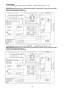
All gas connections must be made according to national and local codes. The gas supply (service) line must be the same
size or greater than the inlet line of the appliance. This range uses a 1/2" NPT inlet (see fig. in this chapter for details of
gas connections installations).On all pipe joints use sealant resistant to LP gas.
1. Manual Shut-off Valve:
This installer-supplied valve must be installed in the gas service line ahead of the appliance in the gas flow and in a
position where it can be reached quickly in the event of an emergency. The manual shut-off valve shall be installed
properly in order to be accessible when the appliance is installed.
2. Pressure Regulator(see fig. in this chapter)
a) All cooking equipment must have a pressure regulator on the incoming service line for safe and efficient
operation, since service pressure may fluctuate with local demand. The pressure regulator is supplied
separately with the appliance; regulator has two female threads ½” NPT; it shall be installed properly in order
to be accessible when appliance is installed in final position.
b) Any conversion required must be performed by your dealer or a qualified licensed plumber or gas service
company. Please provide the service person with this manual before work is started on the range. (Gas
conversions are the responsibility of the dealer or end user.)
c) This range can be used with Natural or LP/Propane gas. It is shipped from the factory adjusted for use with
natural gas.
d) Manifold pressure should be checked with a manometer, natural gas requires 4.0" W.c.P. and LP/Propane
requires 11.0" W.C.P. Incoming line pressure upstream from the regulator must be 1" W.c.P. higher than the
manifold pressure in order to check the regulator. The regulator used on this range can withstand a
maximum input pressure of 1/2 PSI (14.0" W.c.P.) If the line pressure is in excess of that amount, a step-
down regulator will be required.
e) The appliance, its individuai shut-off valve, and pressure regulator must be disconnected from the gas
supply piping system during any pressure testing of that system at pressures in excess of 1/2 psig (3.45
kPa).
f) The appliance must be isolated from the gas supply piping system by closing its individuai manual shut-off
valve during any pressure testing of the gas supply piping system at test pressures equal to or less than 1/2
psig (3.45 kPa).
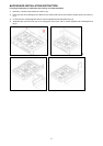
3. Flexible Connections:
a) If the unit is to be installed with flexible couplings and/or quick disconnect fittings, the installer must use a
heavy-duty, AGA design-certified commerciai flexible connector of at least 1/2" (1.3 cm) ID NPT (with
suitable strain reliefs) in compliance with ANSI Z21.41 and Z21.69 standards.
b) In Canada: CAN 1-6.10-88 metal connectors for gas appliances and CAN 1-6.9 M79 quick disconnect
device for use with gas fuel.
CAUTlON: Leak testing of the appliance shall be conducted according to the manufacturer's instructions. Before placing
the oven into operation, always check for leaks with a soapy water solution or other acceptable method. DO NOT USE
AN
OPEN
FLAME TO CHECK FOR LEAKS!
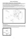
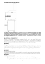
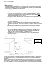
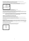
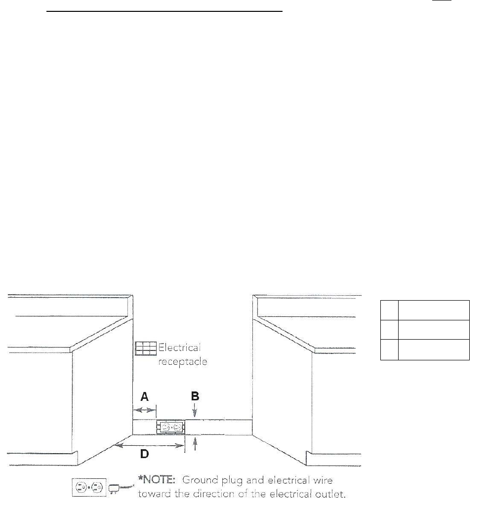
A properly-grounded horizontally- mounted electrical receptacle should be installed no higher than 3" (7.6 cm) above the
floor, no less than
2”( 5 cm)
and no more than
8”(20,3 cm)
from the right side (facing product). Check all local code
requirements.
An agency-approved, properly-sized manual shut-off valve should be installed no higher than 3" (7.6 cm) above the floor
and no less than
2”( 5 cm)
and no more than
8”(20,3 cm)
from the left side (facing product). To connect gas between
shut-off valve and regulator, use agency-approved, properly sized flexible or rigid pipe. Check all local code requirements
A 2”( 5 cm)
B 3”(7,6 cm)
D 8”(20,3 cm)