


4
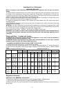
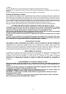
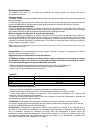
POSITION AND VENTILATION
The cooking appliances that use gas must always remove the products of combustion via a hood linked to
chimneys, chimney flues or via a direct connection to the outside ( see Fig. 5A ). If it is not possible to fit a
hood it is possible to use a fan, fitted on the window or facing directly outside, which operates when the
appliance is in use. ( see Fig. 5B ). In this way the norms in force of the country concerned regarding the
ventilation of premises are strictly followed.
CONNECTING THE APPLIANCE TO THE GAS SUPPLY
Before connecting the appliance to the gas supply you first need to remove the plastic protective
plug for the gas supply which is inserted under pressure in the gas inlet connection. To remove the
plug simply unscrew it.
Then make sure that the details shown on the label on the lower part of the case are compatible with
those of the gas supply.
A label on the last page of this manual and on the lower part of the case indicates the conditions for
regulating the appliance: type of gas and pressure used.
IMPORTANT: This appliance must be installed in accordance with the norms in force of the country
concerned and it must only be used in a well-ventilated place.
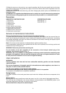
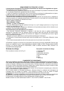
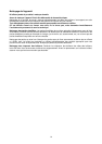
ATTENTION: Remember that the gas inlet connection for the appliance is threaded 1/2 gas
cylindrical male in accordance with the norms UNI-ISO 228-1. (Fig. 6-7)
CONNECTION OF THE APPLIANCE TO THE ELECTRICITY SUPPLY:
Connection to the electricity supply must be carried out according to the norms and indications of
the law in force.
Before carrying out the connection check that:
- The electric charge of the system and the sockets are suitable for the maximum power of the appliance (
see label on the lower part of the case ).
- The socket or system is equipped with an efficient earth connection according to the norms and indications
of the law currently in force. No responsibility can be held if these indications are not respected.
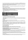
When the connection to the electricity supply is made with a socket.
Fit onto the electric cable a standard plug ( if it is not provided ) which is appropriate for the charge indicated
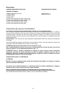
on the label. Connect up the wires according to the diagram in Fig. 8 taking care to respect the
corresponding pairs listed below:
letter L (phase) = brown coloured wire;
letter N (neutral) = blue coloured wire;
symbol”
” earth = green-yellow coloured wire;
- The electric cable must be positioned so that it cannot reach a temperature of over 75 K at any point.
- Do not use reducers, adapters or shunts for the connection as they could cause false contacts and
subsequent dangerous overheating.
When the connection is made directly with the electricity supply:
- To connect the appliance directly to the supply mains, a means for disconnection having a contact
separation in all poles that provide full disconnection under overvoltage category III conditions, must be
incorporated in the fixing wiring, according with the wiring rules.
- Remember that the earth wire must not be interrupted by the switch.
- Alternatively the electrical connection can also be protected by a differential switch of high sensitivity.
- You are strongly advised to fix the special yellow-green earth wire to an efficient earthing system
ATTENTION: The appliance conforms with the regulations of directives 90/396EEC (Gas Directive)
regarding gas appliances for domestic use and the like, 93/68 and 73/23 (Low Voltage Directive) regarding
electrical safety and 2004/108/CE, 93/68 and 89/336 (EMC Directive) regarding electromagnetic
compatibility.
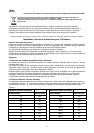
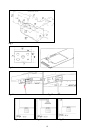
Wiring diagrams Wiring diagram description
For hotplate see Fig. 13. 1. Cable terminal L. Black
2. Ignition switch N. White
3. Spark generator T. Green (earth)
4. Ignition spark